Posts | Comments

Planet Arduino

Archive for the ‘clock hacks’ Category

Have you made an infinity mirror yet? They’re pretty much a rite of passage project at this point. But unlike that DIY power supply, most of them serve no function beyond looking cool (not that there’s anything wrong with that). Might as well make it do something, right?

[How Do You – DIY] has a built a few mirrors because he likes experimenting with the effects of different reflective surfaces in various positions. This time, he’s built a clock from the ground up. Basic infinity mirror rules apply here, though he used semi-transparent reflective film on both sides for greater effect and put an adjustable warping bar in the back so the trail curves toward the center. The actual timekeeping is done by an Arduino Nano.

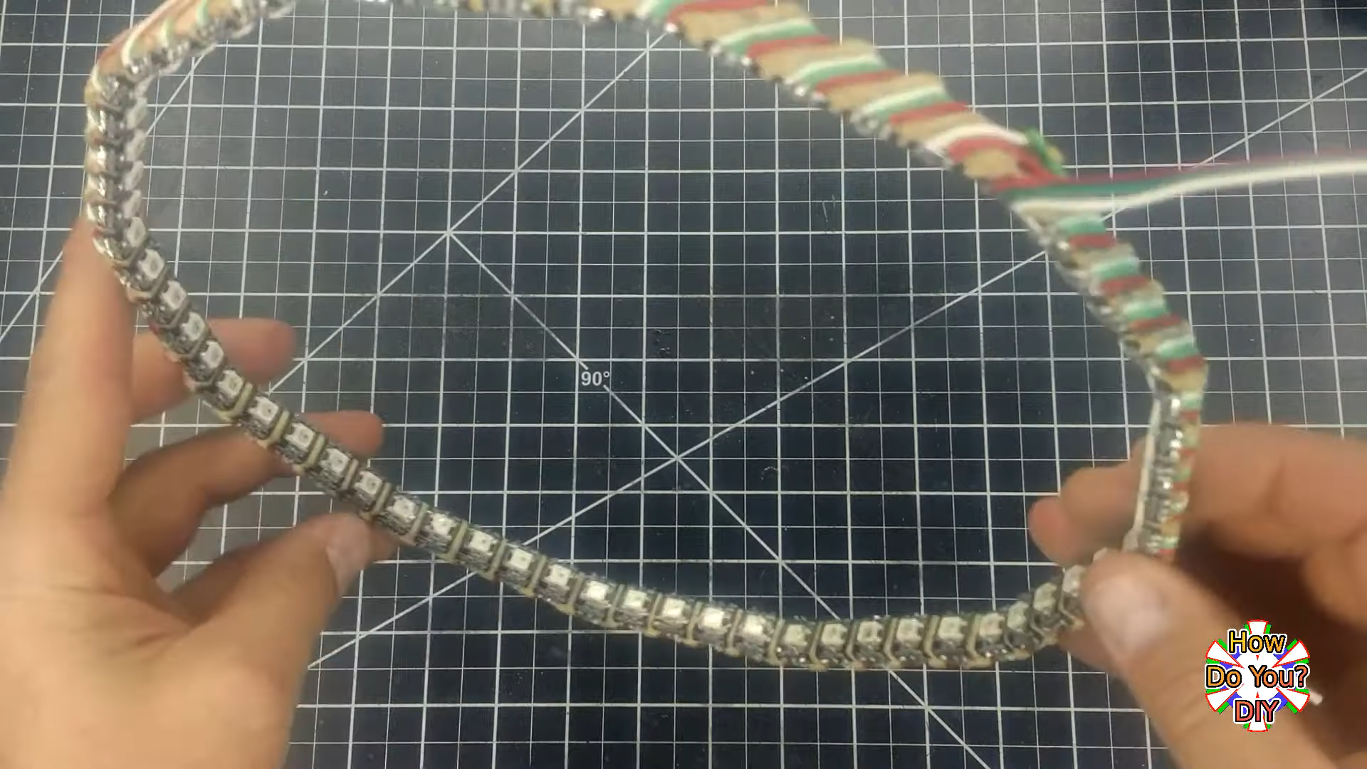
The RGB LEDs on his strip were a few millimeters too far apart for his liking, so he added a few dozen hours to the build by cutting it apart and painstakingly placing them all around the wood frame. Then he Dremeled a groove for each set of three wires that link the LEDs so that they sit flush. The final product is beautiful, and it’s a shame that this LED-holding frame is hidden away inside the equally well-crafted aluminium frame.

Don’t waste another minute — sweep past the break to check out the build video. If it’s a portable and functional conversation piece you want, make a set of infinity mirror coasters.

Oh, and did we mention that we’re running a clock contest? Hint, hint.

For Game of Thrones fans, it’s an awkward time. The show has ended its run on HBO (not without a certain level of controversy), the planned prequel is still years away, and who knows when George R. R. Martin will actually get around to writing the final books in the series. Fans have no choice but to entertain themselves while waiting for further tales of adventure from Westeros, which is how we get things like this motorized clock from [Techarge].

Inspired by the now iconic opening sequence from the HBO series, elements of the 3D printed model spin around while the theme song is played courtesy of a DFPlayer Mini MP3 player module and small 2 watt speaker. The audio hardware, motor, and four digit LED display module in the front are all connected to an Arduino with a custom PCB shield, giving the inside of the clock a very clean and professional appearance.

Around the back side [Techarge] has two small push buttons to set the hour and minutes, and a large toggle to control the music and movement. As of right now it needs to be switched on and off manually, but a future enhancement could see it kick on hourly.  We’d also like to see an RTC module added to the PCB, or better yet, switch over to the ESP8266 and just pull the time down from NTP.

Who knows? By the time you’ve built one of these clocks for yourself, and the hand-made Iron Throne phone charger stand to go with it, maybe ol’ George will have slipped out a new book. But don’t count on it.

If we’ve learned anything over the years, it’s that hackers like weird clocks, and they love packing as many multicolored LEDs into a device as is humanly possible. Combine both of those concepts into one project, and you’ve got a perfect storm. So as far as unnecessarily complex timepieces go, we’d say the “Crazy Clock 4” built by [Fearless Night] ranks up there among the all-time greats.

This Arduino Pro Mini powered clock syncs the current time via GPS, with a temperature compensated DS3231 RTC to keep it on the straight and narrow between satellite downlinks. Once the clock has the correct time, how do you read it? Well, at the top you’ve got a basic numerical readout for the normies, and next to that there’s a circular LED display that looks like it could double as a sci-fi movie prop. On the lower level there’s a binary clock for the real show-offs, and as if that wasn’t enough, there’s even dual color-coded analog meters to show the hours and minutes.

[Fearless Night] has provided everything you need to follow along at home, from the Arduino source code to the 3D models of the case and Gerber files for the custom PCB. Personally we think just the top half of the clock would be more than sufficient for our timekeeping needs. If nothing else it should help save some energy, as the clock currently pulls an incredible 20 watts with all those LEDs firing off.

Should you decide to take a walk down memory lane and check out some of the other interesting LED clocks we’ve featured in the past, you’d be busy for quite awhile. But for our money, it’s still hard to beat the impossibly obtuse single-LED clock.

Time is probably our most important social construct. Our perception of passing time changes with everything we do, and when it comes down to it, time is all we really have. You can choose to use it wisely, or sit back and watch it go by. If you want to do both, build a clock like this one, and spectate in sleek, sophisticated style.

[ChristineNZ]’s mid-century-meets-steampunk clock uses eight ILC1-1/8Ls, which are quite possibly the largest VFD tubes ever produced (and still available as new-old stock). In addition to the time, it displays the date, relative humidity, and temperature in both Celsius and Fahrenheit. A delightful chime sounds every fifteen minutes to remind you that time’s a-wastin’.

The seconds slip by in HH/MM/SS format, each division separated by a tube dedicated to dancing the time away. The mesmerizing display is driven by an Arduino Mega and a MAX6921 VFD driver, and built into a mahogany frame. There isn’t a single PCB in sight except for the Mega — all the VFDs are mounted on wood and everything is wired point-to-point. Sweep past the break to see the progressive slideshow build video that ends with a demo of all the functions.

Those glowing blue-green displays aren’t limited to clocking time. They can replace LCDs, or be scrolling marquees.

In the past, you might very well have started programming in Basic. It wasn’t very powerful language and it was difficult to build big projects with, but it was simple to learn, easy to use, and the interpreter made it easy to try things out without a big investment of time. Today you are more likely to get started using something like an Arduino, but it is easy to miss the accessible language and immediate feedback when you are doing simple projects. Annex WiFi RDS (Rapid Development Suite) is a scripting language for the ESP8266 that isn’t quite Basic, but it shares a lot of the same attributes. One example project from [cicciocb] is a scrolling dot matrix LED clock.

The code is really simple:

' Simple program using Annex and a MAX7219 dot matrix module
' by cicciocb 2019
'Set 4 8x8 displays with GPIO15 as CS pin
MAXSCROLL.SETUP 4, 15
INTENSITY = 5
'Set the first message with Annex
MAXSCROLL.PRINT "Annex"
MAXSCROLL.SHOW 31, INTENSITY
PAUSE 1000
'Set the refresh rate of the display (50 msec) - lower values -> scroll faster
TIMER0 50, SCROLLME
WAIT

SCROLLME:
'Scroll the display with the intensity defined before
MAXSCROLL.SCROLL INTENSITY 
' Set the text with the Date and Time
MAXSCROLL.TEXT DATE$ + " " + TIME$
RETURN

Of course, one reason it is simple is that Annex has a built-in set up for the LED drivers (MAXSCROLL). It also integrates with a remote web browser very easily, so you can embed HTML output in your projects.

If you look at the project’s main page, there is support for a lot of things including devices such as Neopixels, servos, LCDs, and temperature sensors. There’s also support for a lot of protocols and algorithms ranging from MQTT to PID controllers.

If you really miss Basic, you can use it on the web. Not to mention, that QuickBasic is still floating around.

We have had no shortage of clock projects over the years, and this one is entertaining because it spells the time out using Tetris-style blocks. The project looks good and is adaptable to different displays. The code is on GitHub and it relies on a Tetris library that has been updated to handle different displays and even ASCII text.

[Brian] wanted to use an ESP8266 development board for the clock, but the library has a bug that prevents it from working, so he used an ESP32 board instead. The board, a TinyPICO, has a breakout board that works well with the display.

There are also some 3D printed widgets for legs. If we’re honest, we’d say the project looks cool but the technology isn’t revolutionary. What we did find interesting though is that this is a good example of how open source builds on itself.

Of course, the library does a lot of the work, but according to [Brian] the it has several authors. [Tobias Bloom] started the code, and others have changed the library to draw ASCII characters and to support any display that uses the AdaFruit GFX-style library.

So while the code is simple, the result is impressive and is a result of [Brian] leveraging a lot of code from others — a great example of Open Source in action.

We looked at Brian’s use of this library for a YouTube subscription counter, but a clock has more universal appeal, we think — not everyone has a lot of YouTube subscribers. If you don’t have a life, you might try to recreate Tetris using the game of life.

After covering a few of his builds at this point, we think it’s abundantly clear that [Igor Afanasyev] has a keen eye for turning random pieces of antiquated hardware into something that’s equal parts functional and gorgeous. He retains the aspects of the original which give it that unmistakable vintage look, while very slickly integrating modern components and features. His work is getting awfully close to becoming some kind of new art form, but we’re certainly not complaining.

His latest creation takes an old-school “Monopak” electronic flash module and turns it into a desk clock that somehow also manages to look like a vintage television set. The OLED displays glowing behind the original flash diffuser create an awesome visual effect which really sells the whole look; as if the display is some hitherto undiscovered nixie variant.

On the technical side of things, there’s really not much to this particular build. Utilizing two extremely common SSD1306 OLED displays in a 3D printed holder along with an Arduino to drive them, the electronics are quite simple. There’s a rotary encoder on the side to set the time, though it would have been nice to see an RTC module added into the mix for better accuracy. Or perhaps even switch over to the ESP8266 so the clock could update itself from the Internet. But on this build we get the impression [Igor] was more interested in playing with the aesthetics of the final piece than fiddling with the internals, which is hard to argue with when it looks this cool.

Noticing the flash had a sort of classic TV set feel to it, [Igor] took the time to 3D print some detail pieces which really complete the look. The feet on the bottom not only hold the clock at a comfortable viewing angle, but perfectly echo the retro-futuristic look of 50s and 60s consumer electronics. He even went through the trouble of printing a little antenna to fit into the top hot shoe, complete with a metal ring salvaged from a key-chain.

Late last year we were impressed with the effort [Igor] put into creating a retro Raspberry Pi terminal from a legitimate piece of 1970’s laboratory equipment, and more recently his modern take on the lowly cassette player got plenty of debate going. We can’t wait to see what he comes up with next.

Sometimes you have an idea, and despite it not being the “right” time of year you put a creepy skull whose eyes tell the time and whose jaw clacks on the hour into a nice wooden box for your wife as a Christmas present. At least, if you’re reddit user [flyingalbatross1], you do!

The eyes are rotated using 360 degree servos, which makes rotating the eyes based on the time pretty easy. The servos are connected to rods that are epoxied to the spheres used as eyes. Some water slide iris decals are put on the eyes offset from center in order to point in the direction of the minutes/hours. An arduino with a real time clock module keeps track of the time and powers the servos.

Check out the video after the break:

The jaw opens and closes on the hours – springs are screwed to the inside of the jaw to the outside of the skull behind the bones that surround the eyes; they’re hidden when the skull is in its box. A third servo is used as a winch to pull the jaw open from the inside of the bottom of the chin. When it releases, the springs close the mouth and the clack of the teeth replaces an hourly chime.

A bit late (or early) for Halloween, but it’s a really fun project. [Flyingalbatross1] has made the arduino code available, as well as showing plenty of images of how the parts are put together. Take a look at this this atomic clock-in-a-skull, or you make your own talking skull for Halloween!

via Reddit

We’re certainly no strangers to unique timepieces around these parts. For whatever reason, hackers are obsessed with finding new and interesting ways of displaying the time. Not that we’re complaining, of course. We’re just as excited to see the things as they are to build them. With the assumption that you’re just as enamored with these oddball chronometers as we are, we present to you this fantastic digital tachometer clock created by [mrbigbusiness].

The multi-function digital gauge itself is an aftermarket unit which [mrbigbusiness] says you can get online for as little as $20 from some sites. All he needed to do was figure out how to get his Arduino to talk to it, and come up with some interesting way to hold it at an appropriate viewing angle. The mass of wires coming out of the back of the gauge might look intimidating, but thanks to his well documented code it shouldn’t be too hard to follow in his footsteps if you were so inclined.

Hours are represented by the analog portion of the gauge, and the minutes shown digitally were the speed would normally be displayed. This allows for a very cool blending of the classic look of an analog clock with the accuracy of digital. He’s even got it set up so the fuel indicator will fill up as the current minute progresses. The code also explains how to use things like the gear and high beam indicators, so there’s a lot of room for customization and interesting data visualizations. For instance, it would be easy to scrap the whole clock idea and use this gauge as a system monitor with some modifications to the code [mrbigbusiness] has provided.

The gauge is mounted to a small project box with some 3D printed brackets and bits of metal rod, complete with a small section of flexible loom to cover up all the wires. Overall it looks very slick and futuristic without abandoning its obvious automotive roots. Inside the base [mrbigbusiness] has an Arduino Nano, a DS1307 RTC connected via I2C, a voltage regulator, and a push button to set the time. It’s a perfectly reasonable layout, though we wonder if it couldn’t be simplified by using an ESP8266 and pulling the time down with NTP.

We’ve seen gauges turned into a timepiece before, but we have to admit that this is probably the most practical realization we’ve seen of the idea yet. Of course if you want to outfit the garage with something a bit more authentic, you can always repurpose a Porsche brake rotor.

When you show up at a party wearing this bare PCB watch, there are effectively two possible reactions you might receive from the other people there. Either they are going to snicker at the nerd who’s wearing a blinking circuit board on their wrist in public, or they are going to marvel at the ridiculously low part count. We’ll give you one guess as to which reaction you’d likely get at any event Hackaday is involved in.

Designed and built by [Electronoobs], this extremely simple watch consists of a ATmega328P microcontroller, a dozen LEDs with their associated 200 Ω resistors, and a battery. There’s also a single push button on the front which is used to not only set the watch, but turn the LEDs on when you want to check the time. Short of dropping down to one LED and blinking out the time, it’s hard to imagine a timepiece with fewer components than this.

You’re probably wondering how [Electronoobs] pulled this off without an external clock source for the ATmega328P chip. The chip actually has an internal 8 MHz oscillator that can be used, but you need to flash the appropriate bootloader to it first. Accordingly, the backside of the PCB has both SPI and a UART solder pads for external bootloader and firmware programming.

As you might expect, there’s a downside to using the internal oscillator: it’s not very good. The ATmega328P spec sheet claims a factory calibrated accuracy of ±10%, and [Electronoobs] has found that equates to a clock drift of around 15 seconds per day. Not exactly great, but considering the battery only lasts for two days anyway, it doesn’t have much of an impact in this case.

Compared to other “analog” LED watches we’ve seen, the simplicity of this build is really quite remarkable. The closest competitor we’ve seen so far is this slick binary watch.


  • Newsletter

    Sign up for the PlanetArduino Newsletter, which delivers the most popular articles via e-mail to your inbox every week. Just fill in the information below and submit.

  • Like Us on Facebook