After some requests from customers, I have decided to design a small module that can help everyone prototyping and embedding SDI-12 in their own designs. Enter, mini (rewind! I should have posted this piece last year but forgot it was still in draft mode!)!
This mini module measures only 1″ by 1″ (2.54mm*2.54mm) and is a quarter the size of the regular adapter:
mini vs regular
The immediate advantage is you can easily place it on a breadboard for prototyping like this, with an ESP32 dev board:
mini with ESP32 dev board on breadboard
The size of the mini is designed so that there is one hole on the breadboard for each connection. Some dimensions in mm. Notice there are two mounting holes in case you wish to mount this on your circuit board securely:
mini dimensions
The relative locations of the 6-pin ICSP header, the bottom-right mounting hole, and the top right SDI-12 bus hole are unchanged from the regular board so I can still flash firmware on this board using my existing programmer!
Here is how I connected the module to my ESP32:
breadboard for mini
So I first put my ESP32 on the breadboard, with 5V connected to to top red and gnd to top blue. I also connected 3.3V to bottom red (not used) and gnd to bottom blue.
Then I connected 21 to 5V and 25 to gnd, both to top power strips. I also placed a 0.1″ jumper between 21e and 22e, another one between 24e and 25e. This is to make 22 5V and 24 GND, to match the module, and also keep the 22a-24a available to connect a TRS adapter to connect to an SDI-12 sensor.
Also, I connected 22j to gnd on bottom, and 23j (orange wire) to module TX3 which connects to my ESP32 serial port 1 RX, and 24j (yellow wire) to module RX which connects to my ESP32 serial port 1 TX.
mini with ESP32 dev board hooked up
Notice that because of the 0.1″ jumpers, my 22a is 5V and 24a is GND. The original pin on the module for this pin is NC or not connected, so you can jump GND to it with no issues. That also leaves 23a as SDI-12 signal. I then placed a TRS adapter in pins 22a-24a, with tip connecting to 22a (5V), ring connecting to 23a (SDI-12 signal), and 24a to GND:
mini with ESP32 dev board trs adapter and sensor
You can’t really see which pins I connected to ESP32 because my ESP32 dev board doesn’t have silk screen on top. I was using pin 13 for serial port 1 TX and pin 34 for serial port 1 RX. You can use what fits you.
If you want to use a raspberry pi pico instead of an ESP32, here is how I wired them together.
Here is a screen recording on my computer. You can see how I was reading from the mini module and SDI-12 sensors. It’s very similar with both pico and ESP32 dev boards because I am using micropython on them both.
2023 is the ten-year anniversary of the Cave Pearl Project, with hundreds of data loggers built from various parts in the Arduino ecosystem and deployed for Dr. Patricia Beddows‘ research.
Cheap, simple, stand-alone loggers enable teaching and research opportunities that expensive, complex tools can not. However there are a few trade-offs with this minimalist design: Supporting only Analog & I2C sensors make the course more manageable but losing the DS18b20, which has served us so well over the years, does bring a tear to the eye. Removing the SD card from the previous model means you have to think about memory constraints on run-time. The RTC’s one second minimum means this logger is not suitable for high frequency sampling – so you are not going to use it for experiments in eddy flux covariance or seismology. UV exposure makes the 50ml tubes brittle after about four months in full sun, and the coin cell limits operation to environments that don’t go much below freezing – although it’s easy enough to convert the logger to use two lithium AAA’s and we’ve tested those down to -15°C.
See the video below and how to build the loggers in the post here.
Despite the ongoing chip shortage, I’ve secured a batch of processors for more adapters. At the moment I’ve also built enough stock to last for a little while.
So currently I have about 50 qty adapters including a few with analog inputs. I have more boards and ICs but want to conserve my parts. From what I saw, there won’t be a relief of chip shortage until a year from now, i.e. May 2023. I’ve maintained the price of $49 (sometimes $45) for the last decade by absorbing the cost of parts etc. I might be able to continue to do so if I get some help with assembly, such as getting a pick-and-place machine to place surface parts for me. But it’s an expensive machine.
Here is a brief history of my adapters:
In the summer of 2015, I came up with the idea to make a USB adapter that can make reading SDI-12 sensors easier, after having to deal with this protocol in a number of projects. This purple board was the first batch made at oshpark.com. It is a small PCB fab business (they only collect orders and send to actual fab houses) on the west coast. They used to be called dorkbot PDX, a small group of electronics hobbists on the west coast trying to make affordable boards by banding together in their group orders.
First SDI-12 USB adapter prototype in November 2015
This board has the same general layout as the current version, with the miniUSB (maybe my obsession or did I just purchase too many of these connectors?!), USB-UART chip from FTDI, an atmega328p-au, and a programming header. Back then I only had a single terminal for an SDI-12 sensor and had no option to supply external power, well, not easily:
Connecting to external power 2016
Back in the days, I was using a terminal program to talk to the adapter and wrote a macro based of the terminal program to automate data collection. In 2016, I started learning Python more seriously, maybe it’s from raspberry pi, or maybe it was trying to teach physics with some computing elements, or just having to learn it to do projects. So here comes the logging script, in its primitive form in early 2016:
Python script running on Raspberry pi in Feb. 2016
I also started marketing the adapter as compatible with WIN/NIX/MACOS/RPI because back then Python 3.x was able to bring a more consistent programming experience across these systems that Python 2.x was never able to.
Back then, IoT (Internet of Things) was in its very primitive stage and not many places allowed data to be uploaded and presented online. I started with Sparkfun’s Phant server and thingspeak.com, not sure which one first.
Logging data to the internet in April 2016
Later in 2016, I realized there were some need for high precision analog inputs and added the SDI-12 USB + Analog adapter to the lineup. This is the first prototype, in purple as oshpark.com purple. Placing the tiny analog-to-digital adapter used to be nerve wracking. I have since mastered it.
SDI-12 + Analog USB adapter in November 2016
I had a number of interesting projects in 2016-17 and didn’t do a lot on the SDI-12 USB adapters until later in 2017, when I had a project that required collecting GPS data with the sensor so I designed this for the project and general use.
SDI-12 + GPS USB adapter in July 2017
Back then, the basic adapter was still a small half-sized green board with a single SDI-12 terminal. That was able to change:
Full-sized (since then) SDI-12 USB adapter in March 2018
I didn’t market this as a separate adapter because I had high hope that this will replace the more expensive GPS adapter but the hardware didn’t support GPS. So, I started marketing this as a full-sized adapter at the same price point, $49, and gradually retired the half-sized green boards with single terminals. Starting with this version, I added external power connection and a jumper to select between 5V from USB, where most sensors work fine, and the external power terminal, where you can supply your own DC voltage such as 12V. This feature came from the Analog and GPS adapters.
Later in 2018, I redesigned the basic adapter to mostly today’s look and feel. It now has the 4 terminals, power input and selector on the left and right sides, optional basic analog and digital inputs on top, and an extension port in the middle, with an option of UART instead of USB as well.
Very recognizable look of SDI-12 USB adapter in May 2018
Here is a look at two high resolution analog extension boards on top of the basic adapter. I completed updating the code to take inputs and auto scale the inputs, for up to 4 such extension boards:
High resolution analog input extension boards May 2018
I also added extra SDI-12 terminals extension board to help manage the many wires you may have to manage if you want to connect more sensors.
I have also started customizing my adapters to connect to other sensors, such as the following with accelerometers, from special requests.
Customized adapter with accelerometers June 2018
Later that summer, I designed my own data logger! This was based on the idea of having an embedded SDI-12 processing unit, an analog input, and then an ESP32 processor running a new thing called microPython, new and getting traction back then, both the processor and software, now they’ve become major hardware and software players, if not dominating the IoT. This logger is very promising, with WiFi, Xbee, possibility of 4G LTE-M, sd card, real-time clock, and lots of expension!
My own complete WiFi Xbee GSM etc. data logger July 2018
Lots of things have been happening back then and I did a few rounds of firmware development but didn’t end up releasing this logger! Some of you may know that the spirit of this logger lives on and is thriving in a different sector of the industry! The following look may be familiar?
My logger in an SK-16 enclosure August 2018
In early 2019, I added the UART interface adapter to the lineup, based off the same board as USB interfaced adapter, due to an increase of demand to interface with Arduino, ESP32 etc.
UART adapter March 2019
In June, I contemplated using larger terminals based on user feedback. I decided, in order to maintain the same size and look, I can use 0.175″ pitch terminals instead of 0.1″. This makes the terminals accept thicker wires and separate the wires further for installation and prevent short circuits.
Comparison of 0.1″ and 0.175″ pitch terminals July 2019
Now this looks really really like what I’m selling today:
SDI-12 USB Adapter July 2019
I have also been logging data from my own back yard to demonstrate and test my logging scripts:
My backyard sensor run in the summer of 2019
I was even able to determine that after heavy rainfalls I always had power outage on my logger (see long flat blue lines after spikes). It turned out to be a faulty outdoor outlet in my house tripping up the circuit breaker after heavy rain water seeped into it causing short circuit. I later fixed it:
Bad outdoor outlet I replaced in 2019
Good one I installed in 2019
Lots of things were happening later in 2019, besides what you all know, so I didn’t touch my designs until MUCH later, in early 2021. I added a protection diode to fight 12V accidentally damaging the adapter by operators’ errors.
Adapter with protection diode February 2021
As many of use know, IC shortage soon hit the main street manufacturing. Here was a screen grab of the long way, from 2021:
Chip shortage starting showing long lead times, over 1 year, June 2021
Luckily I was well stocked at the year end of 2020! Now it has become a constant thing in the back of my mind, find parts and stock up!
Showing my stock of parts in 2021 to weather the “temporary” shortage in 2021
Over the years, I got a lot of good suggestions from users. Here is one suggestion to try and read data from a phone. This only works on an android and requires a wire between the adapter and the phone, but it’s a good start.
I started experimenting with android phone and my adapter July 2021
Here is another request from users to handle more sensors with easier terminals and combat the environments. I designed this to fit inside a specific enclosure, the same one I used for my own logger, which was now 3-4 yr old and didn’t get an update (I did update it but didn’t build a prototype). I started selling this to a research group for their projects but held back because I didn’t have many chips left (and it may be a lookalike to something else too)!
SDI-12 USB SK-16 adapter February 2022
I was literally counting my chips at this point! Fortunately I found a small batch of the processor in a smaller form factor and decided to take a risk with the supplier. So now we have a new revision. The protection diode has been replaced by a surface mount version but I’ve kept the thruhole part footprint because I bought a batch of the thruhole diodes, just in case. So if you see your board has an orange diode, or no such diode but a small black box on the top right, both are fine!
New design with smaller processor April 2022
The smaller processor takes quite a bit more time to place and I always place it before all other parts so I can turn the board around to see if I placed it perfectly or not. There aren’t any pins on the chip so it’s harder to check. Hopefully when I get a pick and place machine, I don’t have to worry about it.
Size comparison between the two processors April 2022
So there you have it! I forgot I was planning for a brief history. As a closing remark, I’ve seen the gradual shift of users of this adapter from almost entirely academic research to an increasing percentage of applications to more individual users. What’s not changed is that people love simple and inexpensive solutions to their data logging needs and I’m proud that my adapters have met their needs so far! Thanks for your time!
Historical data can be essential to making your electronics and Arduino project work how you want them to. Data retention is one of the features that changes depending on which level of Arduino Cloud account you have. Here’s everything you need to know, so you can choose exactly the right Arduino Cloud plan.
Hang on though. Aren’t we here to talk about data retention?
Indeed we are. When we say “variables”, this is the term used to describe the data you send to your Arduino Cloud. It sounds a bit technical, but consider the word. “Variable” actually makes more sense than “data”, which is kinda woolly.
Variables are information that changes or, you guessed it, varies. Temperature, for example. If you have a temperature sensor sending data to the Cloud, it’s a variable. Because the value of the data (the temperature) is always changing/varying.
So in your sketch it’s known as a variable. The different data retention options in the Arduino Cloud plans tell you how long the Cloud will store a record of those variables for you.
Historical Data Options
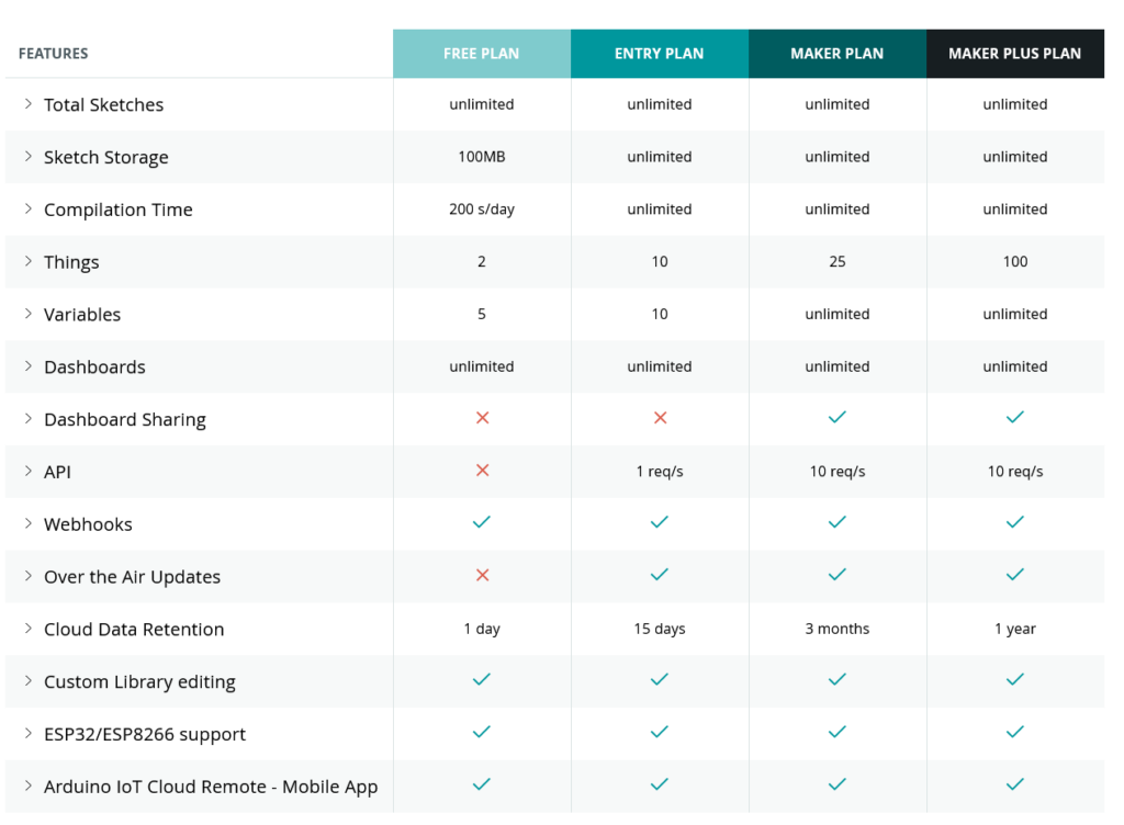
Each Arduino Cloud plan offers a different length of time for how long you retain sensor data, depending on your needs.
If you’re running a home automation to turn the lights on when it drops dark, your system is working with (pretty much) real-time data. So 24 hours of sensor information is perfectly adequate. It’s not like you’ll be turning a lamp on or off based on yesterday’s ambient light levels.
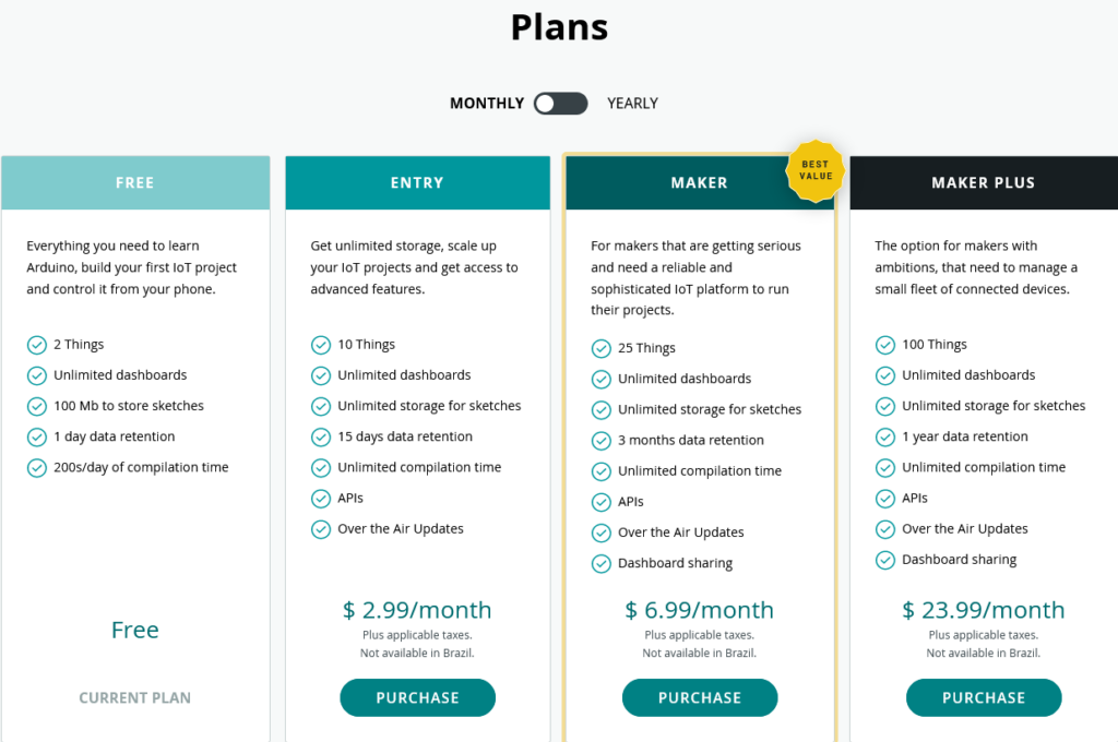
A weather station might work a bit differently though. If you’re measuring the temperature or rainfall or daylight hours, you may want to build a comparison to see how the weather is changing. In this case, an Arduino Cloud Entry plan would give you 15 days of data, allowing you to monitor and record recent changes in your weather station’s variables.
Historical data for an IoT greenhouse, or maybe an aquarium or terrarium, would be much more important. Maybe it’s even an industrial project that’s monitoring equipment for predictive maintenance needs. In these cases, being able to look back at your variables over previous weeks and months could be essential. In that case, you’d go Maker or Maker Plus, so you can build dashboards with detailed histories of your measurements.
It’s very possible that you don’t even know how much historical data will be useful to your project at first. You start on the free tier, decide that it’d be useful to have legacy information, and go up through the Entry plan and eventually settle on Maker. The project leads the way, until it’s delivering everything you need.
Putting Historical Data to Use in Arduino Cloud
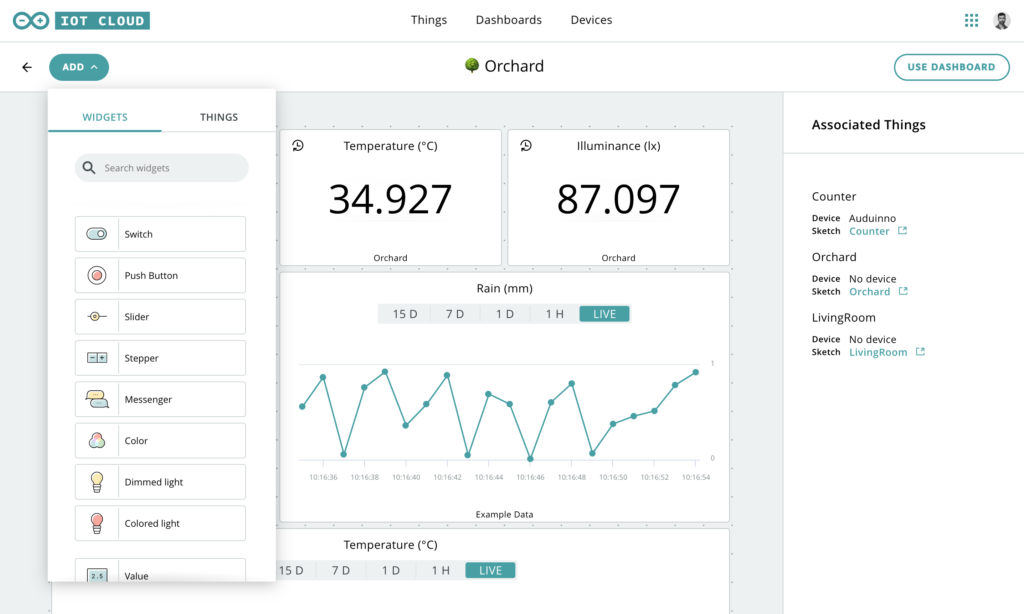
Arduino Cloud is really clever when it comes to the data generated by sensors and used as variables. For example, you can specify how often new data is sent to your Arduino Cloud.
Let’s say you’re monitoring Wi-Fi signal strength at the bottom of the garden, where a project (weather station, let’s say) is installed. If this is a solar and/or battery powered device, power consumption becomes essential. By changing the data sampling interval from updating a variable on Arduino Cloud every second to updating once a minute, you can extend battery life by a huge amount. The device is only operating a fraction of the time it was before, and the information is just as useful.
Combined with 15 days or three months of historical data, you can build a detailed picture of Wi-Fi performance that lets you keep everything running perfectly. Or, if you need to find out when and why your signal has been dropping, the story is right there in your Arduino Cloud dashboard.
Choosing the Right Arduino Cloud Plan
So for all these reasons, you can see why different amounts of data retention are available in the Arduino Cloud plans. It’s not that all projects benefit from as much retention as possible. As we discussed, even some complex, elaborate projects barely need any. Others, which might be simple signal strength monitoring or rainfall measurement, need to know what was happening months ago.
You have the choice, because the different Arduino Cloud plans offer different historical data options for different needs. If in doubt for what your project needs to work as intended, start on the free plan and work up from there.
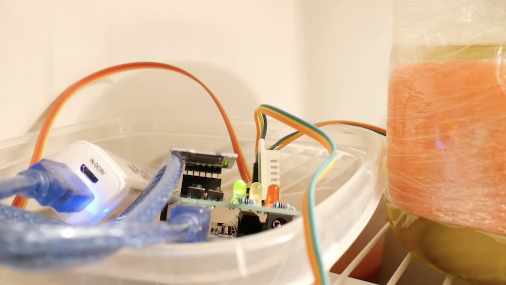
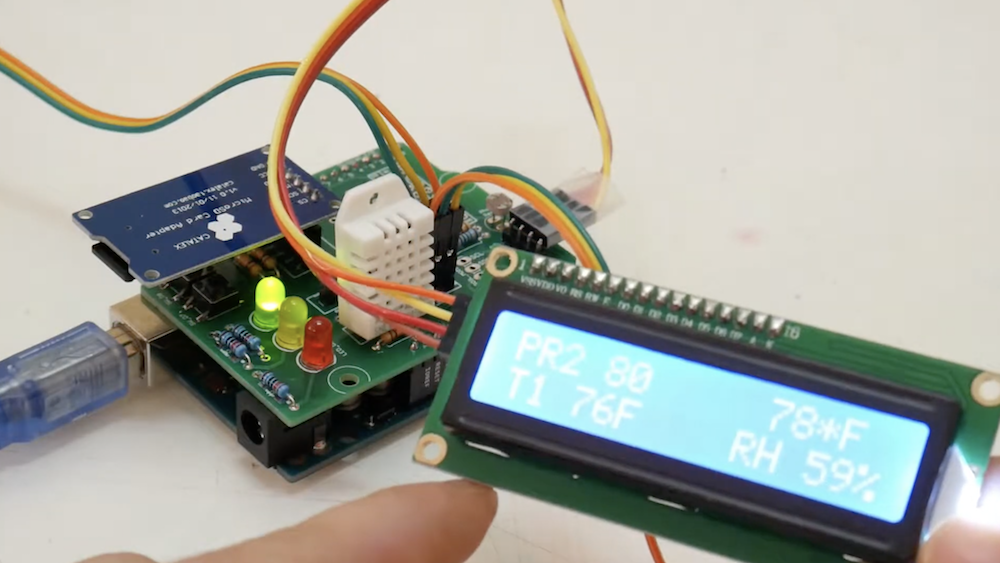
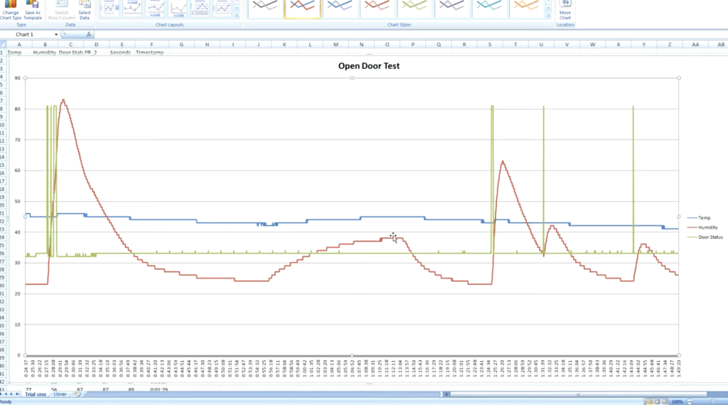
What really happens when you open the refrigerator door? Sure, you know intuitively that cold air escapes, but just how much? And how fast does the food inside actually heat up? To find out, Ryan Bates came up with his own data logging setup using an Arduino Uno, a custom sensor shield, and a microSD card reader.
His device uses a photoresistor to tell when the door has been opened, as well as a DHT22 temperature/humidity sensor to log the air temperature and door status. Along with this, TMP36 sensors are placed around the fridge to get a more granular look at temperatures, including one attached to a pickle jar.
[Stewart] tipped us about his very nice project: pokewithastick. It is an Arduino compatible board (hardware, not footprint) based on the ATMEGA1284P which can be programmed to collect and post data to internet logging sites such as Thingspeak or Xively.
As you can see in the picture above, it has a small 50x37mm footprint (roughly 2″x1.5″). The pokewithastick is composed of an Wiz820 Ethernet module, a micro-SD card slot, 2 serial ports, one battery backed Real Time Clock (RTC), one radio connector (for the usual nRF24L01 2.4GHz radio), one power & user LED and finally a reset button. There are two power rails on the board which can be split (5v + 3.3V) or combined (3.3v only) which may allow you to connect Arduino shields to it. You can program the board using the standard 6-pin header or via a serial programmer if an appropriate (Arduino) bootloader is installed.
The project is open hardware, has been designed using Kicad and all the files can be downloaded as a zip file.
A few years ago, [Phang Moh] and his compatriots were asked by a client if they could make a vehicle tracking device for oil tankers all around Indonesia. The request of putting thousands of trackers on tanks of explosives was a little beyond [Phang Moh]‘s capability, but he did start tinkering around with GPS and GSM on an Arduino.
Now that tinkering has finally come to fruition with [Phang]‘s TraLog shield, a single Arduino shield that combines GPS tracking with a GSM and GPRS transceiver. There’s also an SD card thrown in for good measure, making this one of the best tracking and data logging shields for the Arduino.
The shield can be configured to send GPS and sensor data from devices attached to an I2C bus to remote servers, or a really cool COSM server. [Phang] is selling his TraLog for $150, a fairly good deal if you consider what this thing can do.
Seems like the perfect piece of kit for just about any tracking project, whether you want to know the location of thousands of oil tankers or just a single high altitude balloon.
Planet Arduino is, or at the moment is wishing to become, an aggregation of public weblogs from around the world written by people who develop, play, think on Arduino platform and his son. The opinions expressed in those weblogs and hence this aggregation are those of the original authors. Entries on this page are owned by their authors. We do not edit, endorse or vouch for the contents of individual posts. For more information about Arduino please visit www.arduino.cc
You are currently browsing the archives for the data logging category.