Posts | Comments

Planet Arduino

Archive for the ‘transportation hacks’ Category

Hitag transponders have been used in a wide variety of car keys as a protective measure against hot-wiring and theft. They’re also a reason why it’s a lot more expensive to get car keys duplicated these days for many models that use this technology. However, there is now an open source programmer that works with these transponder keys, thanks to [Janne Kivijakola].

The hack uses an old reader device salvaged from a Renault in a scrapyard, hooked up to an Arduino Mega 2560 or Arduino Nano. With this setup, key transponders can be programmed via a tool called AESHitager, which runs on Windows. It’s compatible with a variety of Hitag transponders, including Hitag2, Hitag3, and Hitag AES, along with the VVDI Super Chip and certain types of BMW keys.

If you’ve been having issues with coded keys, this project might just be what you need to sort your car out. Everything you need is available on GitHub for those wishing to try this at home. We’ve seen some interesting hacks in this space before, too. Video after the break.

The story of how [Tony]’s three-wheeled electric scooter came to be has a beginning that may sound familiar. One day, he was browsing overseas resellers and came across a new part, followed immediately by a visit from the Good Ideas Fairy. That’s what led him to upgrade his DIY electric scooter to three wheels last year, giving it a nice speed boost in the process!

The part [Tony] ran across was a dual brushless drive unit for motorizing a mountain board. Mountain boards are a type of off-road skateboard, and this unit provided two powered wheels in a single handy package. [Tony] ended up removing the rear wheel from his electric scooter and replacing it with the powered mountain board assembly.

He also made his own Arduino-based interface to the controller that provides separate throttle and braking inputs, because the traditional twist-throttle of a scooter wasn’t really keeping up with what the new (and more powerful) scooter could do. After wiring everything up with a battery, the three-wheeled electric scooter was born. It’s even got headlights!

[Tony]’s no stranger to making his own electric scooters, and the fact that parts are easily available puts this kind of vehicular experimentation into nearly anybody’s hands. So if you’re finding yourself inspired, why not order some stuff, bolt that stuff together, and go for a ride where the only limitation is personal courage?

the active foil flying across the water

Earlier in the year, [rctestflight] created an active hydrofoil RC craft but found the actual performance very lacking. Luckily for him and for us, he continued to tweak it and one tweak suddenly turned it from a nightmare to a dream.

That tweak was adding ArduPilot’s airplane model. The design had three servos, which each actuated the angle of a foil underneath one of the three pontoons. The ship propelled itself via some propellers mounted near the top. If you know much about ArduPilot, you notice that active hydrofoil boat doesn’t show up on the list of supported platforms, and you’re right. [rctestflight] points out that the three servos actually function as a plane underwater. The front two are ailerons and the back one is an elevator, all things that ArduPilot knows how to handle with a tightly controlled loop except for one thing; there’s no altitude data.

So he stole a trick he developed earlier for his ground effect plane and used a distance sensor to let ArduPilot know how to adjust things. He used a sonar sensor instead of lidar as it works better with water and he was pleasantly surprised when he took it out on the lake and it just worked wonderfully. The original goal with the active stabilization was to have the efoil immune to choppy waters, and we’re sad to say that it didn’t quite reach that lofty target. The single sonar sensor follows the wave in front of it beautifully but can’t handle the complex waves being thrown at it. Perhaps some sort of sensor fusion algorithm could provide the necessary data to be truly resilient. But we love watching the foil glide across the water and it is hard to remember that it’s actively flying rather than just floating that way.

Others have tried and failed to 3D print a hydrofoil while others have succeeded. We love that [rctestflight] came back to finish the fight and came away a champion. Video after the break.

A little over a a year ago, we covered an impressive battery monitor that [Timo Birnschein] was designing for his boat. With dedicated batteries for starting the engines, cranking over the generator, and providing power to lights and other amenities, the device had to keep tabs on several banks of cells to make sure no onboard systems were dipping into the danger zone. While it was still a work in progress, it seemed things were progressing along quickly.

But we know how it is. Sometimes a project unexpectedly goes from having your full attention to winning an all-expense-paid trip to the back burner. In this case, [Timo] only recently put the necessary finishing touches on his monitor and got it installed on the boat. Recent log entries on the project’s Hackaday.io page detail some of the changes made since the last time we checked in, and describe the successful first test of the system on the water.

Certainly the biggest issue that was preventing [Timo] from actually using the monitor previously was the lack of an enclosure and mounting system for it. He’s now addressed those points with his 3D printer, and in the write-up provides a few tips on shipboard ergonomics when it comes to mounting a display you’ll need to see from different angles.

The printed enclosure also allowed for the addition of some niceties like an integrated 7805 voltage regulator to provide a solid 5 V to the electronics, as well as a loud piezo beeper that will alert him to problems even when he can’t see the screen.

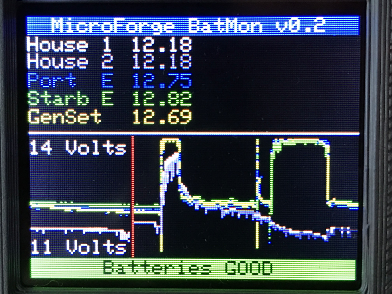
Under the hood he’s also made some notable software improvements. With the help of a newer and faster TFT display library, he’s created a more modern user interface complete with a color coded rolling graph to show voltages changes over time. There’s still a good chunk of screen real estate available, so he’s currently brainstorming other visualizations or functions to implement. The software isn’t using the onboard NRF24 radio yet, though with code space quickly running out on the Arduino Nano, there’s some concern about getting it implemented.

As we said the first time we covered this project, you don’t need to have a boat to learn a little something from the work [Timo] has put into his monitoring system. Whether you’re tracking battery voltages or temperatures reported by your BLE thermometers, a centralized dashboard that can collect and visualize that data is a handy thing to have.

It used to be that upgrading a car stereo was fairly simple. There were only a few mechanical sizes and you could find kits to connect power, antennas, and speakers. Now, though, the car stereo has interfaces to steering wheel controls, speed sensors, rear-view cameras, and more. [RND_ASH] was tired of his 14-year-old system so he took an Android head unit, a tablet, and an Arduino, and made everything work as it was supposed to.

The key is to interface with the vehicle’s CAN bus which is a sort of local area network for the vehicle. Instead of having lots of wires running everywhere, today’s cars are more likely to have less wiring all shared with many devices.

[RND_ASH] has several videos describing the whole project and we expect there will be some more upcoming. You can see part one, below.

The project also reverse engineers how to display on the tiny screen in the dashboard. The code for the CAN bus interface is on GitHub. There’s also a written narrative on what he learned about the Mercedes interface in a different repository.

We’ve seen other cars get similar treatment, of course. If you want a gentle introduction to CAN hacking, we’ve done that, too.

One of the keys to efficient cycling performance is a consistent pedalling cadence. To achieve this the cyclist must always be in the correct gear, which can be tricky when your legs are burning and you’re sucking air. To aid in this task, [Jan Oelbrandt] created Shift4Me, an open-source Arduino powered electronic shifter.

The system consists of a hall effect sensor at the pedals to measure cadence, an Arduino controller, and a servo mechanism to replace the manual shifter. Everything is mounted in a small enclosure on the frame. The only way to get one is to build your own, so a forum is available for Shift4Me builders, where the BOM, instructions, code and other documentation is available for download. Most bikes should be easy to convert, and [Jan] invites builders to post their modifications and improvements.

Since the only input is the cadence sensor, we wonder if the system will interfere more than help when the rider has to break cadence. It does however include allowance to hold on the current gear, or reset to a starting gear by pushing a button. One major downside is that you will be stuck in a single gear if the battery dies since the manual shifter is completely removed.

As one of the oldest continuously used forms of mechanical transport, there is no shortage of bicycle-related hacks. Some of the more recent ones we’ve seen on Hackaday include e-bike with a washing machine motor, and a beautifully engineered steam-powered bicycle.

If we are to believe many science fiction movies, one day throngs of people wearing skin-tight silver spandex jumpsuits will be riding around on hovercraft. Hovercraft haven’t really taken the world by storm, but [Fitim-Halimi] built his own model version and shows you how he did it. You can see the little craft moving in the video below.

In theory, a hovercraft is pretty simple, but in practice they are not as easy as they look. For one thing, you need a lot of air to fill the plenum chamber to get lift. That’s usually a noisy operation. The solution? In this case, a hairdryer gave up its motor for the cause. In addition, once floating on a near-frictionless cushion of air, you have to actually move without contacting the ground. Like many real hovercraft, this design uses another fan to push it along. You can see in the video that the designer uses Jedi hand motions to control the vehicle.

The good news is the motors just go one way, so there is no need for an H-bridge to reverse the motors. A simple FET switch turns them on or off. There is a servo motor to move a rudder that redirects the thrust fan’s air output.

If you want to try this yourself, there are schematics and source code on GitHub. We wondered how hard it would be to put a sensor on board and make an interesting twist on a line following robot, or maybe prevent it from hitting walls. Perhaps a reverse thrust fan would be useful, too. In fact, two extra thrust fans, each 120 degrees apart, could give you interesting options.

We liked the idea of foamboard for the body to reduce weight. We’ve seen meat packing trays used before. If you didn’t read our post on the history of the hovercraft, you might be surprised how old the idea really is. We keep waiting for our winged hovercraft.

Today’s commercial aircraft are packed to the elevators with sensors, computers, and miles and miles of wiring. Inside the cockpit you’re more than likely to see banks of LCDs and push buttons than analog gauges. So what’s that mean for the intrepid home simulator builder? Modern problems require modern solutions, and this 3D printed simulator is about as modern as it gets.

Published to Thingiverse by the aptly named [FlightSimMaker], this project consists of a dizzying number of 3D-printed components that combine into a full-featured desktop simulator for the Garmin G1000 avionics system. Everything from the parking brake lever to the push buttons in the display bezels was designed and printed: over 200 individual parts in all. Everything in this X-Plane 11 compatible simulator is controlled by an Arduino Mega 2560 with the SimVim firmware.

To help with connecting dozens of buttons, toggle switches, and rotary encoders to the Arduino, [FlightSimMaker] uses five CD74HC4067 16-channel multiplexers. The display is a 12.1 inch 1024 x 768 LCD panel with integrated driver, and comes in at the second most expensive part of the build behind the rotary encoders. All told, the estimated cost per display is around $250 USD.

Even if you aren’t looking to build yourself a high-tech flight simulator, there’s plenty of ideas and tips here that could be useful for building front panels. We particularly like the technique used for doing 3D-printed lettering: the part is printed in white, spray painted a darker color, and then the paint is sanded off the faces of the letters to reveal the plastic. Even with a standard 0.4 mm nozzle, this results in clean high-contrast labels on the panel with minimal fuss.

Of course, while impressive, these panels are just the beginning. There’s still plenty more work to do if you want to build an immersive simulation experience. Including, in the most extreme cases, buying a Boeing 737 cockpit.


  • Newsletter

    Sign up for the PlanetArduino Newsletter, which delivers the most popular articles via e-mail to your inbox every week. Just fill in the information below and submit.

  • Like Us on Facebook