Posts | Comments

Planet Arduino

Archive for the ‘transportation hacks’ Category

While those of us stuck sailing desks might not be able to truly appreciate the problem, [Timo Birnschein] was tired of finding that some of the batteries aboard his boat had gone flat. He wanted some way to check the voltage on all of the the batteries in the system simultaneously and display the information in a central location, and not liking anything on the commercial market he decided to build it himself.

Even for those who don’t hear the call of the sea, this is a potentially useful project. Any system that has multiple batteries could benefit from a central monitor that can show you voltages at a glance, but [Timo] is actually going one better than that. With the addition of a nRF24 module, the battery monitor will also be able to wireless transmit the status of the batteries to…something. He actually hasn’t implemented that feature yet, but some way of getting the data into the computer so it can be graphed over time seems like a natural application.

The bill of materials is pretty short on this one. Beyond the aforementioned nRF24 module, the current version of the monitor features an Arduino Nano clone, a 128×160 SPI TFT display, and a handful of passives.

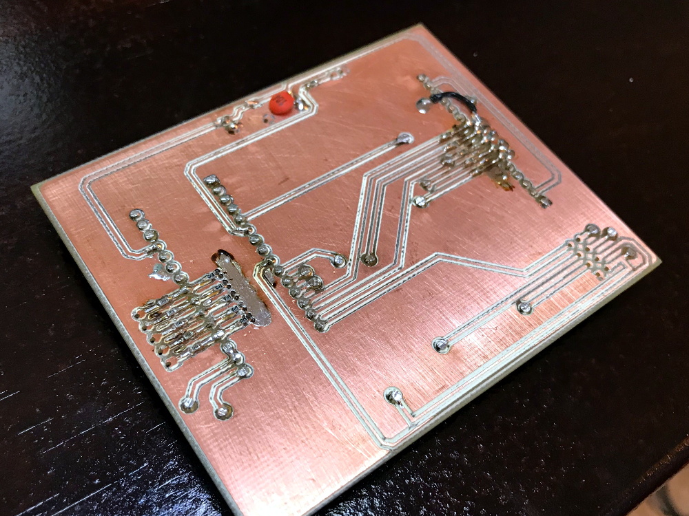
Knowing that a perfboard wouldn’t last long on the high seas, [Timo] even routed his own PCB for this project. We suspect there’s some kind of watertight enclosure in this board’s future, but it looks like things are still in the early phases. It will be interesting to follow along with this one and see how it eventually gets integrated in to the boat’s electrical system.

If you’re looking for a way to keep an eye on the voltages aboard your land ship, this battery monitor disguised as an automotive relay is still the high-water mark in our book.

Clamped or bolted to the stern of the boat, outboard motors offer a very easy and (relatively) economical way of powering small craft. The vast majority of these outboards are gasoline powered, with electric models generally limited to so-called “trolling motors” which are often used to move slowly and quietly during fishing. That might be fine for most people, but not [Olly Epsom].

An engineer focusing on renewable energy by profession, [Olly] wanted to equip his small inflatable dinghy with a suitably powerful “green” propulsion system. Deciding nothing on the market quite met his requirements, especially for what manufacturers were charging, he decided to convert an old gas outboard to electric. Not only did he manage to do it for less money than a turn-key system would have cost, but he ended up with a system specifically geared to his exact requirements. Something he says will come in handy if he ever gets around to converting the dinghy to remote control so he can use it as a wildlife photography platform.

Put simply, an outboard motor consists of a gasoline engine with a vertical shaft that’s coupled to a right-angle gearbox with a propeller on the end. Beyond that they’re a fairly “dumb” piece of gear, so replacing the engine on top with something else should be (at least in theory) a pretty simple job. Especially on the small older model that [Olly] decided to use as a donor unit. The 1974 Johnson 2 HP motor didn’t have any tricky electronics in it to contend with; the thing didn’t even have a clutch.

Once [Olly] had removed the old gas engine from the top of the outboard, he designed an adapter plate in OnShape and had it cut out of aluminum so he could mount a beefy 1 kW 48 V brushless electric motor in its place. Connecting the new electric motor to the carcass of the outboard actually ended up being simpler than putting the original motor on, as this time around he didn’t need to reconnect the cooling pumps which would usually pull water from down by the propeller and recirculate it through the engine.

While the mechanical aspects of this project are certainly cool, we’re especially interested in the control system for this newly electric outboard. It uses a 3.2 inch Nextion color touch screen and Arduino Nano to provide a very slick looking digital “dashboard” which can convey motor status and other information at a glance. Unfortunately, [Olly] says the details on that part of the project will be saved for a future post, leaving us with only a single picture of the system’s interface for us to drool over until then.

We’ve seen the occasional seafaring project that made use of an electric trolling motor, and we’ve even seen an electric drill put in some overtime spinning a prop in the water. Converting gasoline boat over to electric is however a rarity. But much like electric car conversions, such projects may become more common as the cost and complexity of powerful electric propulsion systems continues to fall.

[Thanks to Alex for the tip.]

Beyond pride, the biggest issue keeping adults off small motorized scooters is the fact that their tiny motors usually don’t have the power to move anything heavier than your average eighth grader. That didn’t stop [The_Didlyest] from snapping up this $7 thrift store find, but it did mean the hot pink scooter would need to be beefed up if it had any hope of moving 170 lbs of hacker.

Logically, the first step was fitting a more capable motor. [The_Didlyest] used an electric wheelchair motor which had a similar enough diameter that mounting it was fairly straightforward. The original sprocket and chain are still used, as are the mounting holes in the frame (though they had to be tapped to a larger size). That said, the new motor is considerably longer than its predecessor so some frame metal had to be cut away. This left the scooter without a kickstand and with a few inches of motor hanging out of its left side, but it’s all in the name of progress.

Naturally the upgraded motor needed similarly upgraded batteries to power it, so [The_Didlyest] put together a custom pack using eighteen 18650 cells spot welded together for a total output of 25V. Coupled with a 60A battery management system (BMS), the final 6S 3P configured pack is a very professional little unit, though the liberal application of duct tape keeps it from getting too full of itself.

Unfortunately the original motor controller consisted of nothing but relays, and didn’t allow adjusting speed. So that needed to go as well. In its place is a homebrew speed controller made with three parallel MOSFETs and an Arduino to read the analog value from the throttle and convert that into a PWM signal.

[The_Didlyest] says the rear tire is now in need of an upgrade to transmit all this new power to the road, and some gearing might be in order, but otherwise the scooter rebuild was a complete success. Capable of mastering hills and with a top speed of about 10 MPH, the performance is certainly better than the stock hardware.

Of course this is far from the first time we’ve seen somebody put a little extra pepper on a scooter. Some of them even end up being street-legal rides.

Hybrid vehicles, which combine an eco-friendly electric motor with a gasoline engine for extended range, are becoming more and more common. They’re a transitional technology that delivers most of the advantages of pure electric vehicles, but without the “scary” elements of electric vehicle ownership which are still foreign to consumers such as installing a charger in their home. But one element which hybrids are still lacking is a good method for informing the driver whether they’re running on petroleum or lithium; a way to check at a glance how “green” their driving really is.

[Ben Kolin] and his daughter [Alyssa] have come up with a clever hack that allows retrofitting existing hybrid vehicles with an extremely easy to understand indicator of real-time vehicle efficiency. No confusing graphics or arcade-style bleeps and bloops, just a color-changing orb which lives in the cup holder. An evolved version which takes the form of a smaller “dome light” that sits on the top of the dashboard could be a compelling aftermarket accessory for the hybrid market.

The device, which they are calling the ecOrb, relies on an interesting quirk of hybrid vehicles. The OBD II interface, which is used for diagnostics on modern vehicles, apparently only shows the RPM for the gasoline engine in a hybrid. So if the car is in motion but the OBD port is reporting 0 RPM, the vehicle must be running under electric power.

With a Bluetooth OBD adapter plugged into the car, all [Ben] and [Alyssa] needed was an Arduino Nano clone with a HC-05 module to read the current propulsion mode in real-time. With some fairly simple conditional logic they’re able to control the color of an RGB LED based on what the vehicle is doing: green for driving on electric power, purple for gas power, and red for when the gas engine is at idle (the worst case scenario for a hybrid).

Check out our previous coverage of OBD hacking on the Cadillac ELR hybrid if you’re looking to learn more about what’s possible with this rapidly developing class of vehicle

Racing is certainly exciting for the person rocketing around the track fast enough to get the speedometer into the triple digits, and tends to be a decent thrill for the spectators if they’ve got good seats. But if you’re just watching raw race videos on YouTube from the comfort of your office chair it can be a bit difficult to appreciate. There’s a lack of context for the viewer, and it can be hard to get the same sense of speed and position that you’d have if you saw the event first hand.

In an effort to give his father’s racing videos a bit more punch, [DusteD] came up with a clever way of adding video game style overlays to the recordings. The system provides real-time speed, lap times, and even a miniature representation of the track complete with a marker to show where the action is taking place. The end result is that recordings of Dad’s exploits on the track could pass as gameplay footage from Gran Turismo (we know GT doesn’t have motorcycles, but you get the idea).

The first part of the system is the tracker itself, which consists of a GPS receiver, an Arduino Pro Micro, and an SD card module. [DusteD] powers the device with two 18650 cells in parallel, and a DC-DC boost converter to step it up to 5V. Everything is contained in a 3D printed enclosure that he designed in OpenSCAD, with the only external elements being a toggle switch, a momentary switch, and most critically, a set of LEDs.

These LEDs play into the second part of the system, the software. The blinking LEDs are positioned so they’ll get picked up by the camera, which is then used to help synchronize the data stored on the SD card with the video. [DusteD] came up with some software that will take the speed and position information from the card, and turn it into PNG files with transparent backgrounds. These are then placed on top of the video with the help of FFmpeg. It takes a little adjustment to get everything lined up properly, but as the video after the break shows the end result is very impressive.

This build reminds us of the Raspberry Pi powered GPS helmet camera we featured a few years back, and it’s interesting to see how the two projects achieved what’s essentially the same goal in different ways.

Surely our readers are well aware of all the downsides of owning an airplane. Certainly the cost of fuel is a big one. Birds are a problem, probably. That bill from the traveling propeller sharpener is a killer too…right? Alright fine, we admit it, nobody here at Hackaday owns an airplane. But probably neither do most of you; so don’t look so smug, pal.

But if you did own a plane, or at least work at a small airport, you’d know that moving the things around on the ground is kind of a hassle. Smaller planes can be pulled by hand, but once they get up to a certain size you’ll want some kind of vehicle to help out. [Anthony DiPilato] wanted a way to move around a roughly 5,200 pound Cessna 310, and decided that all the commercial options were too expensive. So he built his own Arduino powered tank to muscle the airplane around the tarmac, and his journey from idea to finished product is absolutely fascinating to see.

So the idea here is pretty simple. A little metal cart equipped with two beefy motors, an Arduino Mega, a pair of motor controllers, and a HC-08 Bluetooth module so you can control it from your phone. How hard could it be, right? Well, it turns out combining all those raw components into a little machine that’s strong enough to tow a full-scale aircraft takes some trial and error.

It took [Anthony] five iterations before he fine tuned the design to the point it was able to successfully drag the Cessna without crippling under the pressure. The early versions featured wheels, but eventually it was decided that a tracked vehicle would be required to get enough grip on the blacktop. Luckily for us, each failed design is shown along with a brief explanation about what went wrong. Admittedly it’s unlikely any of us will be recreating this particular project, but we always love to see when somebody goes through the trouble of explaining what went wrong. When you include that kind of information, somewhere, somehow, you’re saving another maker a bit of time and aggravation.

Hackers absolutely love machines with tank treads. From massive 3D printed designs to vaguely disturbing humanoid robots, there’s perhaps no sweeter form of locomotion in the hacker arsenal.

Tired of risking his life every time he had to signal a turn using his hands while riding his bicycle in rainy Vancouver, [Simon Wong] decided he needed something a bit higher tech. But rather than buy something off the shelf, he decided to make it into his first serious Arduino project. Given the final results and the laundry list of features, we’d say he really knocked this one out of the park. If this is him getting started, we’re very keen to see where he goes from here.

So what makes these turn signals so special? Well for one, he wanted to make it so nobody would try to steal his setup. He wanted the main signal to be easily removable so he could take it inside, and the controls to be so well-integrated into the bike that they wouldn’t be obvious. In the end he managed to stuff a battery pack, Arduino Nano, and an HC-05 module inside the handlebars; with just a switch protruding from the very end to hint that everything wasn’t stock.

On the other side, a ATMEGA328P microcontroller along with another HC-05 drives two 8×8 LED matrices with MAX7219 controllers. Everything is powered by a 18650 lithium-ion battery with a 134N3P module to bring it up to 5 VDC. To make the device easily removable, as well as keep the elements out, all the hardware is enclosed in a commercial waterproof case. As a final touch, [Simon] added a Qi wireless charging receiver to the mix so he could just pull the signal off and drop it on a charging pad without needing to open it up.

It’s been some time since we’ve seen a bike turn signal build, so it’s nice to see one done with a bit more modern hardware. But the real question: will he be donning a lighted helmet for added safety?


It is pretty easy to go to a big box store and get a digital speedometer for your bike. Not only is that no fun, but the little digital display isn’t going to win you any hacker cred. [AlexGyver] has the answer. Using an Arduino and a servo he built a classic needle speedometer for his bike. It also has a digital display and uses a hall effect sensor to pick up the wheel speed. You can see a video of the project below.

[Alex] talks about the geometry involved, in case your high school math is well into your rear view mirror. The circumference of the wheel is the distance you’ll travel in one revolution. If you know the distance and you know the time, you know the speed and the rest is just conversions to get a numerical speed into an angle on the servo motor. The code is out on GitHub.

Granted, reading a magnet, keeping time, and driving a servo isn’t exactly cutting edge. On the other hand, it made us think about what other kinds of outputs you could drive. We haven’t seen a nixie tube speedometer (well, not on a bicycle, anyway), for example. Or maybe one built with mechanical flip numbers like an old clock.

We have seen some with Arduinos and lots of LEDs (although, again, not really for a bicycle). This speedometer might still be our favorite, though.


Filed under: Arduino Hacks, transportation hacks

A tachometer used to be an accessory added to the dash of only the sportiest of cars, but now they’re pretty much standard equipment on everything from sleek coupes to the family truckster. If your daily driver was born without a tach, fear not – a simple Arduino tachometer is well within your reach.

The tach-less vehicle in question is [deepsyx]’s Opel Astra, which from the video below seems to have the pep and manual transmission that would make a tach especially useful. Eschewing the traditional analog meter display or even a digital readout, [deepsyx] opted to indicate shift points with four LEDs mounted to a scrap of old credit card. The first LED lights at 4000 RPM, with subsequent LEDs coming on at each 500 RPM increase beyond that. At 5800 RPM, all the LEDs blink as a redline warning.  [Deepsyx] even provides a serial output of the smoothed RPM value, so logging of RPM data is a possible future enhancement.

The project is sensing engine speed using the coil trigger signal – a signal sent from the Engine Control Unit (ECU) which tells one of the ignition coilpacks to fire. The high voltage signal from the coilpack passes on to the spark plug, which ignites the air-fuel mixture in that cylinder. This is a good way to determine engine RPM without mechanical modifications to the car. Just make sure you modify the code for the correct number of cylinders in your vehicle.

Simple, cheap, effective – even if it is more of a shift point indicator than true tachometer, it gets the job done. But if you’re looking for a more traditional display and have a more recent vintage car, this sweeping LED tachometer might suit you more.

[via r/Arduino]


Filed under: Arduino Hacks, transportation hacks

Now here’s a really cool home hack. [Luis Rodrigues] has automated his garage door to open, simply by flashing his headlights at it.

But wait, doesn’t that mean anyone could break into his house? Nope. At first we thought he had just added some photo-sensors and a bit of computer logic in order to turn a pattern of lights into an output to open the garage, but no, it’s actually specific to his car only. Which is awesome because if anyone ever tried to copy him to break in, all they break into is a very confused state of mind.

You see how it actually works is the headlight output is connected to a control box under the hood of his car. A Moteino (RF Arduino variant) reads the input signal of the headlights flashing three times, and then communicates wirelessly to the garage door in order to open it.

But [Luis] also has a gate outside his property — so if you hold the lights on for a second, both the garage door and the external gate will open as well.

Pretty awesome — mind you, is a garage door button really that much harder to use? This is definitely safer if someone steals your car and happens to have your address though!


Filed under: Arduino Hacks, home hacks, transportation hacks


  • Newsletter

    Sign up for the PlanetArduino Newsletter, which delivers the most popular articles via e-mail to your inbox every week. Just fill in the information below and submit.

  • Like Us on Facebook