Posts | Comments

Planet Arduino

Archive for the ‘display’ Category

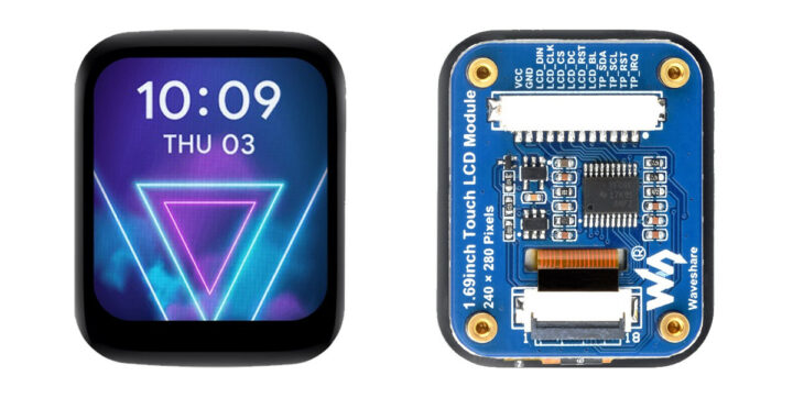
Waveshare 240×280 , IPS, 1.69inch Round LCD Display Module with Touch Paneel

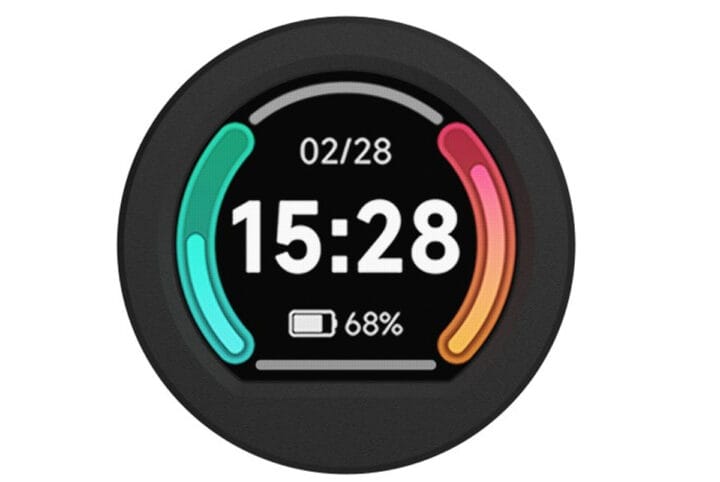
The Waveshare 1.69-inch IPS touch LCD is a 1.69-inch rounded display with 240×280 resolution and a 262K color range. The display driver (ST7789V2) and touch controller (CST816T) are integrated on-board and rely on SPI and I2C interfaces that make it compatible with popular platforms such as Raspberry Pi, Arduino, ESP32, STM32, and more. Previously we have covered many similar display modules like the MaTouch ESP32-S3, T-RGB ESP32-S3, and ESP32-S3 Round SPI TFT. Feel free to check these out if you are looking for a specific rounded display product. Waveshare 1.69-inch IPS touch LCD specifications Display 1.69-inch round LCD with 240×280 resolution and IPS panel. 262K color depth Display Driver –  ST7789V2 SPI display driver Touch Control – CST816T I2C capacitive touch controller for responsive input. Onboard Logic Level Converter  – Onboard voltage translator for 3.3V/5V power, works with Raspberry Pi, ESP32-S3, Raspberry Pi Pico, Arduino, STM32, and more. Dimensions – 41.13 x 33.13 [...]

The post $15 Waveshare 1.69-inch IPS touch LCD module works with Raspberry Pi, Arduino, ESP32, STM32, and other platforms appeared first on CNX Software - Embedded Systems News.

Waveshare RP2040 LCD 0.99 B Rounded Display

The Waveshare RP2040-LCD-0.99-B rounded display is the latest display module by Waveshare. This board is built around the Raspberry Pi RP2040 MCU and hosts a 128×115 pixels 65K color IPS LCD, along with a QMI8658C IMU, all inside a CNC metal case with an acrylic dull-polish bottom plate. The board also hosts a USB Type-C connector, an LDO, a 2MB NOR-Flash, a SH1.0 6PIN connector (adapting 4x GPIO pins), and a BOOT button. Waveshare RP2040-LCD-0.99-B rounded display module specification: Microcontroller – Raspberry Pi RP2040 dual-core Arm Cortex M0+ processor up to 133 MHz with 264KB SRAM Storage – 2MB on-board flash memory Display – 0.99-inch 128×115 pixel 65K color IPS LCD USB – 1x USB 1.1 Type-C port (host/device) for power and programming using drag-and-drop via USB mass storage Sensor – QMI8658C IMU Expansion – 4x GPIO via SH1.0 6PIN connector Power Management – Low-power sleep and dormant modes Dimension – [...]

The post Raspberry Pi RP2040-powered 0.99″ rounded display is housed in CNC metal case appeared first on CNX Software - Embedded Systems News.

Raspberry Pi Pico ESP32-S3 quad display board

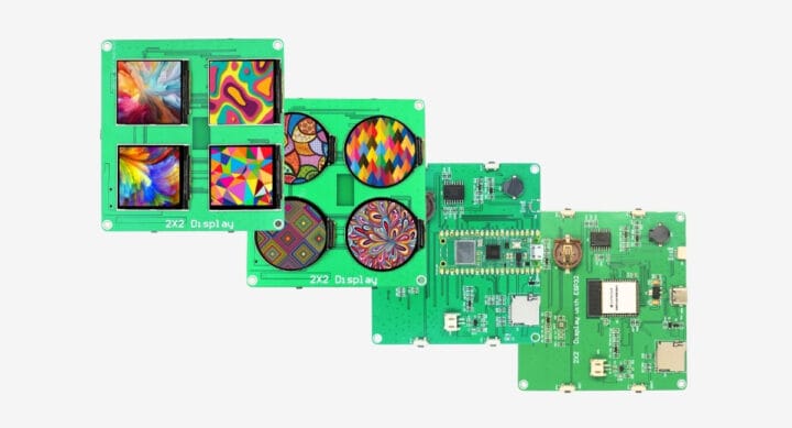
SB Components’ 2×2 Quad Display Board is an MCU development board fitted with either a Raspberry Pi Pico W board or an ESP32-S3-WROOM-1 module used to drive four small color displays in square or round shapes. The board specifically features either four 1.54-inch square TFT displays or four 1.28-inch round displays, a microSD card, an RTC with coin-cell battery holder, and a USB-C port for power and programming, plus a few buttons. It may feel like it’s coming out of the but-why-because-we-can department, but the company expects it to be used for signage, interactive displays, art projects, portable devices, data loggers, education, and more. 2×2 Quad Display Board specifications: Main control (one or the other) Raspberry Pi Pico W MCU – Raspberry Pi RP2040 dual-core Cortex-M0+ microcontroller @ 133 MHz with 264KB SRAM Storage – 2MB QSPI flash Wireless – WiFi 4 and Bluetooth LE 5.2 USB – 1x Micro [...]

The post 2×2 Quad Display Board uses Raspberry Pi Pico W or ESP32-S3-WROOM-1 module to drive four displays (Crowdfunding) appeared first on CNX Software - Embedded Systems News.

Mike Rankin posts on GitHub a wall charger mount version of a CO2 monitor has been slowly evolving for a while.

It started out as a sensor on a Qwiic (STEMMA QT) connector but was too messy with the two cables. This version uses a make USB-C connector and is design to push onto a wall charger. No cord or cables of any kind required and to upload a new sketch you can plug it into the side of your laptop.

See more on GitHub.

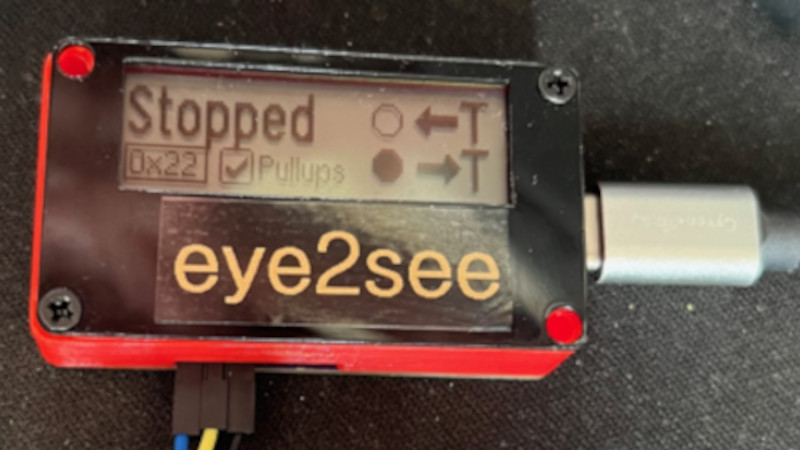
For as popular as the Arduino platform is, it’s not without its problems. Among those is the fact that most practical debugging is often done by placing various print statements throughout the code and watching for them in the serial monitor. There’s not really a great way of placing breakpoints or stepping through code, either. But this project, known as eye2see, hopes to change that by using the i2c bus found in most Arduinos to provide a more robust set of debugging tools.

The eye2see software is set up to run on an Arduino or other compatible microcontroller, called the “probe”, which is connected to the i2c bus on another Arduino whose code needs to be debugged. Code running on this Arduino, which is part of the eye2see library, allows it to send debugging information to the eye2see probe. With a screen, the probe can act as a much more powerful debugger than would otherwise typically be available, being able to keep track of variables in the main program, setting up breakpoints, and outputting various messages on its screen.

The tool is not without its downsides, though. The library that needs to run on the host Arduino slows down the original program significantly. But for more complex programs, the tradeoff with powerful debugging tools may be worth it until these pieces of code can be removed and the program allowed to run unencumbered. If you’d like to skip needing to use a second Arduino, we’ve seen some other tools available for debugging Arduino code that can run straight from a connected PC instead.

Scoreboards seem to be quite popular as beginner projects but the results are often very specific to the hardware used and very ‘hard coded’ to the original purpose.

It seemed to me that there are some parts of this style of application that are generic and probably independent to the type of scoreboard (sport and/or hardware used). I wanted to explore which parts and how this could drive a generic framework to create and update any scoreboard.

Scoreboard basics

A scoreboard is a large board, for example at a sports ground or stadium, on which the score in a game or match is displayed for the audience and participants. This display is typically square or rectangular in shape and contains all of the information relevant the sport/game such as home and guest score, game elapsed time, quarter/half indicator, other clock information, etc.

A good scoreboard is simple – it should be easy to read and quick to understand. It should contain clear information specific to the game being played and may include important game metrics. These metrics can greatly complicate the layout and size of displays for some sports – in my experience Cricket is an extreme example (shown below).

So what’s generic about this?

For simplicity I’ll just consider a sports scoreboard similar to the type shown below.

Analyzing the data displayed by this style of scoreboard, we can see a limited range of types of information:

  • Numeric Fields. By far the majority of information on a scoreboard consists of numeric fields.
  • Clocks. There is usually at least one game clock (duration or countdown) and often a second clock (eg, a shot clock in basketball).
  • Static Elements. These are labels (Home, Guest, Score, etc) and separation lines that don’t change during the course of the game. These invariant elements are often built into the physical construction of the scoreboard.
    Some labels may be static just for one match (player names, team names) and these are often handled using replaceable signs or as text fields on software driven displays.
  • Graphical Elements. Some data elements may be represented in graphical form such as dots, lines or icons. The underlying data is usually numeric (for example true/false or a count).

Building a framework

The framework described here is included in the scoreboard examples (the file scoreboard.h in MD_MAXPanel_SB_*) accompanying the MD_MAXPanel library. While the current framework uses a 40×32 LED panel as the scoreboard, it should be straightforward to change for alternative output hardware.

Defining the Scoreboard

For me, a useful framework takes the display and clock management functions away from the application and allows it concentrate on the functionality required for the scoreboard operator.

So, as a starting point, this means that all display field management will happen within the framework code (a C++ class in this implementation). Fields in this class are represented as a linked list of field attributes created by the application when defining the scoreboard. Each entry in the list is given a unique application defined numeric identifier id by the application.

  enum fieldType_t
  {
    NUMBER,   ///< a simple number
    MMMSS,    ///< time MMM:SS displayed
    MMSS,     ///< time MM:SS displayed
    SS        ///< time SS display only
  };

  struct field_t
  {
    uint8_t id;       ///< identifier
    fieldType_t type; ///< field type
    uint8_t x, y;     ///< field coordinates
    uint32_t value;   ///< current value of the field
    bool leadZero;    ///< field has leading zeroes
    uint8_t size;     ///< field size in characters/numbers
    field_t* next;    ///< next in the list
  };

The field has a coordinate x, y for its top left corner, a size (displayed characters), including the colon for time and leading zeroes if specified. The type of field determines how to interpret and display its current value. For clocks the current time is uniformly stored in seconds but can be displayed in the different formats specified.

A clock is a field that has associated with it additional information. A game clock will have a timeLimit it counts up to (or down from), a boolean status of whether it is stopped, and some in ternal management.

  struct clock_t
  {
    field_t* f;           ///< field associated with this timer
    uint32_t timeLimit;   ///< upper limit for time
    uint32_t timeLast;    ///< last time displayed/updated
    uint32_t timeToGo;    ///< time to go before next update
    bool countUp;         ///< counting up if true
    bool stopped;         ///< true if stopped
  };

To define a scoreboard an application needs to define the displayed fields (using fieldCreate()) and then associate a clock with those fields that are clocks (clockCreate()).

Managing Field Values

Fields only contain numeric values, so simple class methods to manage each field are fieldSetValue(), fieldGetValue() and fieldValueAdd() which do the obvious suggested by the method name.

Managing Clocks

For the clock fields the value is managed by the class rather than the application, although the field*() methods will still work correctly.

The clock value is incremented or decremented each second by the class. The application manipulates the status of a clock using

  • clockStart() to stat the clock running.
  • clockStop() to stop the clock running.
  • clockToggle() to runs the clock if stopped and stops it if running.
  • clockReset() to set the clock to the appropriate value depending on whether it is counting up or down.
  • isClockRunning() to check its run status.

Display Updates

The application repeatedly calls the update() method to allow the class to run its management functions and update the display as required.

Updates are optimized to only change the display hardware when there has been a change to the scoreboard data. All changes occurring between after a call to update() are output at the next call to update().

Sample Applications

Simple scoreboard

The first application is a simple scoreboard showing 2 scores and a clock in MMSS format that counts up from zero time (example code MD_MAXPanel_SB_Simple).

The layout was planned using a spreadsheet to locate the fields and static elements of the display.

The prototype operator interface consists of a few tact switches managed by the MD_UISwitch library as follows:

  • Clock Control – one switch to start and stop the clock. A long press resets the clock to zero.
  • Score Up – one switch per score field to add +1 to the score.
  • Score Down – One switch per score field to add -1 to the score. A long press resets the associated score to zero.

The final scoreboard is shown below. The static elements (lines) are drawn by the application during initialization.

Basketball scoreboard

To test the framework concepts further a more complex basketball scoreboard was created with 2 different clocks, more fields, more static elements and some graphical output (example code MD_MAXPanel_SB_BBall).

The display was planned on a spreadsheet, as before.

The operator interface consists of a few tact switches managed by the MD_UISwitch library as follows:

  • Clock Control – one switch to start and stop the clock. A long press resets the clock to zero.
  • Period Count Up – Increment the period counter. Once it reaches 4 it resets back to 0. The period is shown graphically as a sequence of 4 rectangles under the shot clock.
  • Timeout Count Up – One switch per team to add +1 to the timeouts. Timeouts are reset to 0 once they reach 2. Timeouts are shown graphically as a line of 3 dots above the score.
  • Score Up – One switch per score field to add +1 to the score.
  • Score Down – One switch per score field to add -1 to the score. A long press resets the associated score to zero.
  • Team Foul Up – One switch to increment the team foul count. Once this reaches 9 it resets to 0.
  • Shot Clock Reset – One switch top reset the shot clock.
  • Shot Clock Start/Stop – One switch to start and stop the shot clock.

Graphical elements are managed by the application as I could not find a ‘nice’ way to do this in the management class without creating excessive complexity in the class and how it is used.

The final scoreboard is shown below.

Conclusion

The results from this experiment are a bit of a mixed bag for me.

In simple applications, just showing scores and clocks, the framework works well and is a useful tool to simplify the management of the scoreboard.

However, if scoreboard graphical elements are included, I feel that the application still needs to do too much work outside of the management class, bringing it back into the ‘hard coded’ territory I was trying to avoid at the outset.

I may need to revisit this in future…

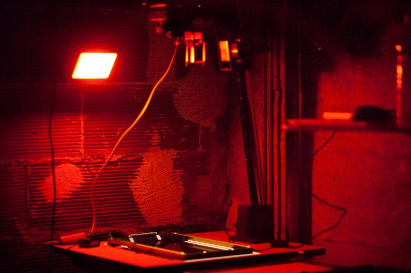
As the world becomes more and more digital, there are still a few holdouts from the analog world we’ve left behind. Vinyl records are making quite the comeback, and film photography is still hanging on as well. While records and a turntable have a low barrier for entry, photography is a little more involved, especially when developing the film. But with the right kind of equipment you can bridge the gap from digital to analog with a darkroom setup that takes digital photographs and converts them to analog prints.

The project’s creator, [Muth], has been working on this project since he found a 4K monochrome display. These displays are often used in resin 3D printers, but he thought he could put them to use developing photographs. This is much different from traditional darkroom methods, though. The monochrome display is put into contact with photo-sensitive paper, and then exposed to light. Black pixels will block the light while white pixels allow it through, creating a digital-to-analog negative of sorts. With some calibration done to know exactly how long to expose each “pixel” of the paper, the device can create black-and-white analog images from a digital photograph.

[Muth] notes that this method isn’t quite as good as professional print, but we wouldn’t expect it to be. It creates excellent black-and-white prints with a unique method that we think generates striking results. The 4K displays needed to reproduce this method aren’t too hard to find, either, so it’s fairly accessible to those willing to build a small darkroom to experiment. For those willing to go further, take a look at some other darkroom builds we’ve seen in the past.

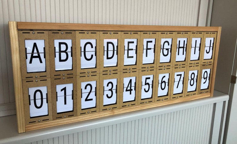
LED and LCD displays are a technological marvel. They’ve brought the price of televisions and monitors down to unheard-of levels since the days of CRTs, but this upside arguably comes with an aesthetic cost. When everything is covered in bland computer screens, the world tends to look a lot more monotonous. Not so several decades ago when there were many sharply contrasting ways of displaying information. One example of this different time comes to us by way of this split-flap display that [Erich] has been recreating.

Split-flap displays work by printing letters or numbers on a series of flaps that are attached to a spindle with a stepper motor. Each step of the motor turns the display by one character. They can be noisy and do require a large amount of maintenance compared to modern displays, but have some advantages as well. [Erich]’s version is built out of new acrylic and MDF, and uses an Arduino as the control board. A 3D printer and CNC machine keep the tolerances tight enough for the display to work smoothly and also enable him to expand the display as needed since each character display is fairly modular.

Right now, [Erich]’s display has 20 characters on two different rows and definitely brings us back to the bygone era where displays of this style would have been prominent in airports and train stations. This display uses a lot of the basics from another split flap display that we featured a few years ago but has some improvements. And, if you’d prefer restorations of old displays rather than modern incarnations, we have you covered there as well.

Thanks to [Bob] for the tip!

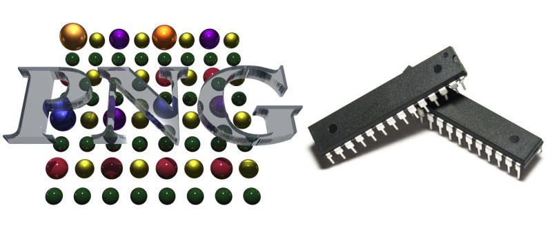
Want to display a PNG file on a display attached to an Arduino or other microcontroller board? You’ll want to look at [Larry Bank]’s PNGdec, the Arduino-friendly PNG decoder library which makes it much easier to work with PNG files on your chosen microcontroller.

The PNG image format supports useful features like lossless compression, and was generally developed as an improved (and non-patented) alternative to GIF files. So far so great, but it turns out that decoding PNG files on a microcontroller is a challenge due to the limited amount of memory compared to desktop machines. When the PNG specification was developed in the 90s, computers easily had megabytes of memory to work with, but microcontrollers tend to have memory measured in kilobytes, and lack high-level memory management. [Larry]’s library addresses these issues.

PNGdec is self-contained and free from external dependencies, and also has some features to make converting pixel formats for different display types easy. It will run on any microcontroller that can spare at least 48 K of RAM, so if that sounds useful then check out the GitHub repository for code and examples.

We’ve seen [Larry]’s wonderful work before on optimizing GIF playback as well as rapid JPEG decoding, and these libraries have increasing relevance as hobbyists continue to see small LCD and OLED-based displays become ever more accessible and affordable.

[PNG logo: PNG Home Site]


  • Newsletter

    Sign up for the PlanetArduino Newsletter, which delivers the most popular articles via e-mail to your inbox every week. Just fill in the information below and submit.

  • Like Us on Facebook