29
Archive for the ‘code’ Category
29
02
Script to query Gerber file outer dimensions
code, kicad, manufacturing, pcb, script Comments Off on Script to query Gerber file outer dimensions
At Wayne & Layne, we design a lot of circuit boards. During the request-for-quote (RFQ) process for getting a PCB fabricated, the outside dimensions of the PCB are an important driver of the overall per-unit price. As part of the W&L “prepare PCB for RFQ” process, we have a little script that uses the PCB’s board outline Gerber file to determine the dimensions of the PCB’s bounding box.
Pass in the filename of the PCB “board outline” Gerber file, and it will print out the dimensions in both the original units (decimills for Gerbers exported from Kicad) as well as inches (again, assuming decimills). It does this by analyzing all the lines of the gerber file, and determining the minimum and maximum in both x and y directions. The script is based on a little chunk of code written by @laen on Twitter (who makes no claim to the code, and also runs the most excellent OSH Park PCB service). We’re releasing this script into the Public Domain, use it however you like.
#!/usr/bin/env python # Gerber query script # Usage: ./gerber_query.py board_edges.gbr # Written by Matthew Beckler for Wayne and Layne, LLC # Based on a script from @laen # Released into the Public Domain. Have fun def main(): import sys if len(sys.argv) < 2: print "Usage: %s gerberfile" % sys.argv[0] sys.exit() import re filename = sys.argv[1] xmin = None xmax = None ymin = None ymax = None with open(filename, 'r') as fid: for line in fid: results = re.search("^X(\d+)Y([\d-]+)", line) if results: x = int(results.group(1)) y = int(results.group(2)) if not xmin or x < xmin: xmin = x if not ymin or y < ymin: ymin = y if not xmax or x > xmax: xmax = x if not ymax or y > ymax: ymax = y print "Board dimensions:" w = xmax - xmin h = ymax - ymin print " ", (w, h), "original units" print " (%.4f, %.4f) inches" % (w / 10000.0, h / 10000.0) print " (%.4f, %.4f) mm" % (w / 10000.0*25.4 , h / 10000.0*25.4) if __name__ == "__main__": main() |
10
I have recently received the following question from a reader: I’m looking for a circuit board design that will need to turn on an array of LEDs when motion is detected during the day time, and also stay on continuously during the night time; using the Arduino would be nice. The project that I am […]
The post Motion and Light Sensors with Arduino (and Without) appeared first on Tinker Hobby.
08
LED Patterns Using DIP Switch and Arduino
arduino, Beginner, code, DIP switch, sketch, video Comments Off on LED Patterns Using DIP Switch and Arduino
When I posted the “LED Control Using DIP Switch” sketch last year (a simple setup the turned on the LED corresponding to that switch position), I also had a slightly modified version of it in which the DIP switch controlled six different light patterns on the LEDs (scroll right, left, in, out, back and forth and random). It presented a “cleaned-up” version of the code using for loops and compared it to the “long-hand” version, showing the trade-off between ease of understanding and conciseness. Except that… I forgot to post it.
Last week someone contacted me asking a question about a similar project he is working on and when I wanted to refer him to this modified sketch I realized it wasn’t on the blog. (Here’s the original sketch and schematic for reference).
What follows below is the missing blog post (not anymore), a comparison between the more readable sketch (easier for beginners to understand) and the more concise version, in a series of snippets showing the main differences between the two versions of the sketch.
The concise version generates a binary sketch that occupies approximately 25% less memory and is almost half as long in lines of code. The entire source code listings are at the very bottom of this post.
Note: the line above each snippet reflects the modification that shortened the sketch.
1) not using #define directives for the LED and switch pins on the Arduino in order to use for loops:
    } else {
     // default: off
     digitalWrite(LED1, LOW);
     digitalWrite(LED2, LOW);
     digitalWrite(LED3, LOW);
     digitalWrite(LED4, LOW);
     digitalWrite(LED5, LOW);
     digitalWrite(LED6, LOW);
   }
|
    } else {
     // default: off
     for (i = 13; i >= 8; i--) {
       digitalWrite(i, LOW);
     }
|
2) using a state variable array (and consequently a for loop) as opposed to individual state variables:
s1state = digitalRead(S1); s2state = digitalRead(S2); s3state = digitalRead(S3); s4state = digitalRead(S4); s5state = digitalRead(S5); s6state = digitalRead(S6); |
   for (i = 0, j = 7; i < 6, j >= 2; i++, j--) {
     state[i] = digitalRead(j);
   }
|
3) if (x) versus if (x == 1) (when x is either 0 or 1, then the (x == 1) expression can be written as simply (x)):
    } else if (s5state == 1) {
     // scroll back and forth
|
    } else if (state[4]) {
     // scroll back and forth
|
4) long, repetitive code to randomly turn on or not each LED (for a random duration up to 300 milliseconds) replaced with for loop:
    } else if (s6state == 1) {
     // random
     randomSeed(analogRead(3));
     onoroff = random(0, 2);
     millisecs = random(0, 301);
     digitalWrite(LED1, onoroff);
     delay(millisecs);
     randomSeed(analogRead(3));
     onoroff = random(0, 2);
     millisecs = random(0, 301);
     digitalWrite(LED2, onoroff);
     delay(millisecs);
     randomSeed(analogRead(3));
     onoroff = random(0, 2);
     millisecs = random(0, 301);
     digitalWrite(LED3, onoroff);
     delay(millisecs);
     randomSeed(analogRead(3));
     onoroff = random(0, 2);
     millisecs = random(0, 301);
     digitalWrite(LED4, onoroff);
     delay(millisecs);
     randomSeed(analogRead(3));
     onoroff = random(0, 2);
     millisecs = random(0, 301);
     digitalWrite(LED5, onoroff);
     delay(millisecs);
     randomSeed(analogRead(3));
     onoroff = random(0, 2);
     millisecs = random(0, 301);
     digitalWrite(LED6, onoroff);
     delay(millisecs);
   }
|
    } else if (state[5]) {
     // random
     for (i = 13; i >= 8; i--) {
       randomSeed(analogRead(i - 8));
       onoroff = random(0, 2);
       millisecs = random(0, 301);
       digitalWrite(i, onoroff);
       delay(millisecs);
     }
   }
|
Here’s the full long version:
- Binary sketch size: 3654 bytes
- Code size was sacrificed in order to improve readability for beginners
- Sketch length: 205 lines
  // www.TinkerHobby.com
  // Natalia Fargasch Norman
  // LED control via DIP switches

  // Arduino pins used for the LEDs
  #define LED1 13
  #define LED2 12
  #define LED3 11
  #define LED4 10
  #define LED5 9
  #define LED6 8

  // Arduino pins used for the switches
  #define S1 7
  #define S2 6
  #define S3 5
  #define S4 4
  #define S5 3
  #define S6 2

  // State of each switch (0 or 1)
  int s1state;
  int s2state;
  int s3state;
  int s4state;
  int s5state;
  int s6state;

  // Random values for LED state and delay
  long onoroff;
  long millisecs;

  void setup() {
    // pins for LEDs are outputs
    pinMode(LED1, OUTPUT);
    pinMode(LED2, OUTPUT);
    pinMode(LED3, OUTPUT);
    pinMode(LED4, OUTPUT);
    pinMode(LED5, OUTPUT);
    pinMode(LED6, OUTPUT);
    // pins for switches are inputs
    pinMode(S1, INPUT);
    pinMode(S2, INPUT);
    pinMode(S3, INPUT);
    pinMode(S4, INPUT);
    pinMode(S5, INPUT);
    pinMode(S6, INPUT);
  }

  void loop() {
    s1state = digitalRead(S1);
    s2state = digitalRead(S2);
    s3state = digitalRead(S3);
    s4state = digitalRead(S4);
    s5state = digitalRead(S5);
    s6state = digitalRead(S6);
    if (s1state == 1) {
      // scroll right
      digitalWrite(LED1, HIGH);
      delay(250);
      digitalWrite(LED1, LOW);
      digitalWrite(LED2, HIGH);
      delay(250);
      digitalWrite(LED2, LOW);
      digitalWrite(LED3, HIGH);
      delay(250);
      digitalWrite(LED3, LOW);
      digitalWrite(LED4, HIGH);
      delay(250);
      digitalWrite(LED4, LOW);
      digitalWrite(LED5, HIGH);
      delay(250);
      digitalWrite(LED5, LOW);
      digitalWrite(LED6, HIGH);
      delay(250);
      digitalWrite(LED6, LOW);
    } else if (s2state == 1) {
      // scroll left
      digitalWrite(LED6, HIGH);
      delay(250);
      digitalWrite(LED6, LOW);
      digitalWrite(LED5, HIGH);
      delay(250);
      digitalWrite(LED5, LOW);
      digitalWrite(LED4, HIGH);
      delay(250);
      digitalWrite(LED4, LOW);
      digitalWrite(LED3, HIGH);
      delay(250);
      digitalWrite(LED3, LOW);
      digitalWrite(LED2, HIGH);
      delay(250);
      digitalWrite(LED2, LOW);
      digitalWrite(LED1, HIGH);
      delay(250);
      digitalWrite(LED1, LOW);
    } else if (s3state == 1) {
      // scroll in
      digitalWrite(LED1, HIGH);
      digitalWrite(LED6, HIGH);
      delay(250);
      digitalWrite(LED1, LOW);
      digitalWrite(LED6, LOW);
      digitalWrite(LED2, HIGH);
      digitalWrite(LED5, HIGH);
      delay(250);
      digitalWrite(LED2, LOW);
      digitalWrite(LED5, LOW);
      digitalWrite(LED3, HIGH);
      digitalWrite(LED4, HIGH);
      delay(250);
      digitalWrite(LED3, LOW);
      digitalWrite(LED4, LOW);
    } else if (s4state == 1) {
      // scroll out
      digitalWrite(LED3, HIGH);
      digitalWrite(LED4, HIGH);
      delay(250);
      digitalWrite(LED3, LOW);
      digitalWrite(LED4, LOW);
      digitalWrite(LED2, HIGH);
      digitalWrite(LED5, HIGH);
      delay(250);
      digitalWrite(LED2, LOW);
      digitalWrite(LED5, LOW);
      digitalWrite(LED1, HIGH);
      digitalWrite(LED6, HIGH);
      delay(250);
      digitalWrite(LED1, LOW);
      digitalWrite(LED6, LOW);
    } else if (s5state == 1) {
      // scroll back and forth
      digitalWrite(LED1, HIGH);
      delay(250);
      digitalWrite(LED1, LOW);
      digitalWrite(LED2, HIGH);
      delay(250);
      digitalWrite(LED2, LOW);
      digitalWrite(LED3, HIGH);
      delay(250);
      digitalWrite(LED3, LOW);
      digitalWrite(LED4, HIGH);
      delay(250);
      digitalWrite(LED4, LOW);
      digitalWrite(LED5, HIGH);
      delay(250);
      digitalWrite(LED5, LOW);
      digitalWrite(LED6, HIGH);
      delay(250);
      digitalWrite(LED6, LOW);
      digitalWrite(LED5, HIGH);
      delay(250);
      digitalWrite(LED5, LOW);
      digitalWrite(LED4, HIGH);
      delay(250);
      digitalWrite(LED4, LOW);
      digitalWrite(LED3, HIGH);
      delay(250);
      digitalWrite(LED3, LOW);
      digitalWrite(LED2, HIGH);
      delay(250);
      digitalWrite(LED2, LOW);
    } else if (s6state == 1) {
      // random
      randomSeed(analogRead(3));
      onoroff = random(0, 2);
      millisecs = random(0, 301);
      digitalWrite(LED1, onoroff);
      delay(millisecs);
      randomSeed(analogRead(3));
      onoroff = random(0, 2);
      millisecs = random(0, 301);
      digitalWrite(LED2, onoroff);
      delay(millisecs);
      randomSeed(analogRead(3));
      onoroff = random(0, 2);
      millisecs = random(0, 301);
      digitalWrite(LED3, onoroff);
      delay(millisecs);
      randomSeed(analogRead(3));
      onoroff = random(0, 2);
      millisecs = random(0, 301);
      digitalWrite(LED4, onoroff);
      delay(millisecs);
      randomSeed(analogRead(3));
      onoroff = random(0, 2);
      millisecs = random(0, 301);
      digitalWrite(LED5, onoroff);
      delay(millisecs);
      randomSeed(analogRead(3));
      onoroff = random(0, 2);
      millisecs = random(0, 301);
      digitalWrite(LED6, onoroff);
      delay(millisecs);
    } else {
      // default: off
      digitalWrite(LED1, LOW);
      digitalWrite(LED2, LOW);
      digitalWrite(LED3, LOW);
      digitalWrite(LED4, LOW);
      digitalWrite(LED5, LOW);
      digitalWrite(LED6, LOW);
    }
  }
And here’s the full “cleaned-up” version:
- Binary sketch size: 2826 bytes
- Sketch length: 119 lines
  // www.TinkerHobby.com
  // Natalia Fargasch Norman
  // LED control via DIP switches

  // Arduino pins used for the LEDs
  // LED1 13
  // LED2 12
  // LED3 11
  // LED4 10
  // LED5 9
  // LED6 8

  // Arduino pins used for the switches
  // S1 7
  // S2 6
  // S3 5
  // S4 4
  // S5 3
  // S6 2

  // State of each switch (0 or 1)
  int state[6];

  // Random values for LED state and delay
  long onoroff;
  long millisecs;

  // loop counters
  int i, j;

  // delay
  int d = 250;

  void setup() {
    // pins for LEDs are outputs
    // LEDs 1-6 on pins 13-8
    for (i = 13; i >= 8; i--) {
      pinMode(i, OUTPUT);
    }
    // pins for switches are inputs
    // switches 1-6 on pins 7-2
    for (i = 7; i >= 2; i--) {
      pinMode(i, INPUT);
    }
  }

  void loop() {
    for (i = 0, j = 7; i < 6, j >= 2; i++, j--) {
      state[i] = digitalRead(j);
    }

    if (state[0]) {
      // scroll right
      for (i = 13; i >= 8; i--) {
        digitalWrite(i, HIGH);
        delay(d);
        digitalWrite(i, LOW);
      }

    } else if (state[1]) {
      // scroll left
      for (i = 8; i <= 13; i++) {
         digitalWrite(i, HIGH);
         delay(d);
         digitalWrite(i, LOW);
       }

   } else if (state[2]) {
       // scroll in
       // light up LEDs on pins i and 8+(13-i)
       for (i = 13; i >= 11; i--) {
        digitalWrite(i, HIGH);
        digitalWrite(21 - i, HIGH);
        delay(d);
        digitalWrite(i, LOW);
        digitalWrite(21 - i, LOW);
      }

    } else if (state[3]) {
      // scroll out
      // light up LEDs on pins i and 8+(13-i)
      for (i = 11; i <= 13; i++) {
         digitalWrite(i, HIGH);
         digitalWrite(21 - i, HIGH);
         delay(d);
         digitalWrite(i, LOW);
         digitalWrite(21 - i, LOW);
       }

    } else if (state[4]) {
       // scroll back and forth
       for (i = 13; i >= 8; i--) {
        digitalWrite(i, HIGH);
        delay(d);
        digitalWrite(i, LOW);
      }
      for (i = 9; i <= 12; i++) {
        digitalWrite(i, HIGH);
        delay(d);
        digitalWrite(i, LOW);
      }

    } else if (state[5]) {
       // random
       for (i = 13; i >= 8; i--) {
        randomSeed(analogRead(i - 8));
        onoroff = random(0, 2);
        millisecs = random(0, 301);
        digitalWrite(i, onoroff);
        delay(millisecs);
      }

    } else {
      // default: off
      for (i = 13; i >= 8; i--) {
        digitalWrite(i, LOW);
      }
    }
  }
Check out the video of this sketch in action.
LED Patterns Using DIP Switch and Arduino originally appeared on Tinker Hobby on November 8, 2011.
31
Arduino Serial Display: Introducing the GLO-216 2×16 Multifont Serial OLED Display
arduino, code, OLED, OLED display, sketch Comments Off on Arduino Serial Display: Introducing the GLO-216 2×16 Multifont Serial OLED Display
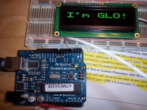 The GLO-216 2×16 Multifont Serial OLED allows you to translate 9600bps serial data into bright, high-contrast text on a compact screen. This low cost, low power serial display comes in two font colors (yellow and green) and is made and sold by seetron.com, owned by Scott Edwards of Electronics Now and Nuts & Volts fame.
Think of the GLO-216 as a “mini terminal” that displays text and custom characters and responds to control characters such as tabs, linefeeds, carriage returns, backspace, etc. It is compatible with RS-232, Stamps, PICs and Arduino; pretty much any serial out, really.
The display uses less than 50mA, so it can be connected straight to the Arduino‘s power supply.
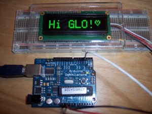
The GLO-216 can store startup text and custom characters in EEPROM and there are instructions to save and recall this information. The simple sketch created to test the display creates and saves a new heart shaped custom character, then displays it on the screen along with some text.
Seetron.com has set up a special offer for tinkerhobby.com readers: you can save 20% off a GLO-216 if you use promo code “HOBBYIST” upon check out. For more information and to purchase, see the GLO-216 product page.
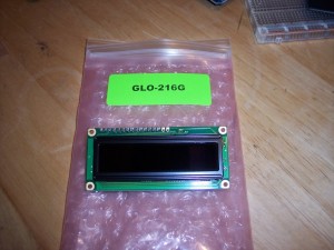
Here’s the GLO-216G just out of the box:
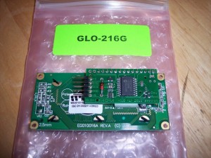
And here’s the view from the back, notice the small board that brings out the pins nicely to a 5-pin header and saves you some soldering work:
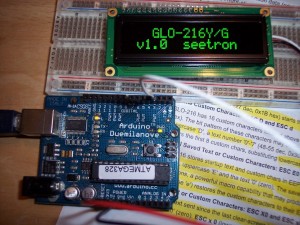
This is what it looks like when you first power it on:
And here’s the result of running the sketch I included in this post, that defines and prints a custom character:
The sketch to drive the display uses the “newsoftserial” library, which can be found here: http://arduiniana.org/libraries/newsoftserial
A few nice features of the newsoftserial library compared to the original softserial are more accurate timing, smaller code size, but best of all the ability to output “inverted” serial (the Arduino documentation states that their serial output is not RS-232 compatible, but newsoftserial permits the Arduino to output inverted serial).
Sketch:
// Test of the GLO-216G serial OLED display
// Natalia Fargasch Norman @ tinkerhobby.com

// GLO-216Y/G information: http://www.seetron.com/glo216.html
// Programming reference: http://seetron.com/glo216/glo216prog.html

#include <SoftwareSerial.h>
#include <GLO216.h>

#define rxPin 255
#define txPin 3
#define NULL 0x00

int inverted = 1;

SoftwareSerial mySerial = SoftwareSerial(rxPin, txPin, inverted);

void setup() {
  pinMode(txPin, OUTPUT);
  digitalWrite(txPin, LOW);
  mySerial.begin(9600);
  delay(10);

  // clears the screen and select font size and style
  char instr1[] = {
    clearScreen(),
    defaultSize(),
    selectSize(), // tall
    selectSize(), // wide
    selectSize(), // big
    textStyle(),
    NULL
  };
  const char message[] = "Hi GLO!";
  mySerial.print(instr1);
  // print message according to prior instructions
  mySerial.print(message);

  // defines a new custom heart shaped character
  char instr2[] = {
    // escape sequence to receive new custom character
    escape(),'D','0',
    // heart pattern using tool at http://seetron.com/apps/app_cceditor.html
    0x80,0x8A,0x95,0x91,0x8A,0x84,0x80,0x80,
    NULL
  };
  // print character 0x80, the newly defined heart
  const char msg[] = {0x80, NULL};
  mySerial.print(instr2);
  // print message according to prior instructions
  mySerial.print(msg);

/*  delay(3000);

  char instr3[] = {
    clearScreen(),
    NULL
  };
  mySerial.print(instr3);*/
}

void loop() {
  // ...
}
GLO216 functions:
// GLO-216G serial OLED display
// Natalia Fargasch Norman @ tinkerhobby.com

// GLO-216Y/G information: http://www.seetron.com/glo216.html
// Programming reference: http://seetron.com/glo216/glo216prog.html

/*
Parameters for setPosition and rightAlign instructions:
setPosition: position + 0x40
rightAlign: '0'-'7'
*/

/*
Parameters for escape instructions:
Define lower custom character: 'D', '0'-'7'
Define upper custom character: 'd', '0'-'7'
Recall saved text: 'E', '0'
Restore custom character set: 'e', '0'
Save text since last clearScreen: 'X', '0'
Store custom character set: 'x', '0'
*/

// Moves printing position to the first character of top line
char homeCursor() {
  return 0x01;
}

// Cycles the font size: normal -> tall -> wide -> big -> normal -> ...
char selectSize() {
  return 0x02;
}

// Sets font size to default of small on two lines of 16 characters
char defaultSize() {
  return 0x03;
}

// Behaves like the backspace key
char backspace() {
  return 0x08;
}

// Moves printing position to the next multiple of 4 location
char tab() {
  return 0x09;
}

// Moves the printing position down a line
char linefeed() {
  return 0x0A;
}

// Moves the printing position up a line
char verticalTab() {
  return 0x0B;
}

// Clears the screen and moves printing position to 0
char clearScreen() {
  return 0x0C;
}

// Moves to the first printing position of the next line
char carriageReturn() {
  return 0x0D;
}

// Turns on the OLED driver circuitry when it has been previously turned off
char turnOn() {
  return 0x0E;
}

// Turns off the OLED driver circuitry to save power
char turnOff() {
  return 0x0F;
}

// Sets the printing position according to value of next byte
char setPosition() {
  return 0x10;
}

// Prints text at the righthand end of a field of defined size from 2-8
char rightAlign() {
  return 0x12;
}

// Sets seven segment style font for large characters
char sevenSeg() {
  return 0x13;
}

// Sets text style font for large characters
char textStyle() {
  return 0x14;
}

// Begin multi-part instruction
char escape() {
  return 0x1B;
}

// See http://seetron.com/glo216/bpigloupgg.html
char bpkInstr() {
  return 0xFE;
}
Header file:
// GLO-216G serial OLED display
// Natalia Fargasch Norman @ tinkerhobby.com

// GLO-216Y/G information: http://www.seetron.com/glo216.html
// Programming reference: http://seetron.com/glo216/glo216prog.html

#ifndef GLO216_h
#define GLO216_h

// Moves printing position to the first character of top line
char homeCursor();

// Cycles the font size: normal -> tall -> wide -> big -> normal -> ...
char selectSize();

// Sets font size to default of small on two lines of 16 characters
char defaultSize();

// Behaves like the backspace key
char backspace();

// Moves printing position to the next multiple of 4 location
char tab();

// Moves the printing position down a line
char linefeed();

// Moves the printing position up a line
char verticalTab();

// Clears the screen and moves printing position to 0
char clearScreen();

// Moves to the first printing position of the next line
char carriageReturn();

// Turns on the OLED driver circuitry when it has been previously turned off
char turnOn();

// Turns off the OLED driver circuitry to save power
char turnOff();

// Sets the printing position according to value of next byte
char setPosition();

// Prints text at the righthand end of a field of defined size from 2-8
char rightAlign();

// Sets seven segment style font for large characters
char sevenSeg();

// Sets text style font for large characters
char textStyle();

// Begin multi-part instruction
char escape();

// See http://seetron.com/glo216/bpigloupgg.html
char bpkInstr();

#endif
Keywords file:
#######################################
# Syntax Coloring Map for GLO216
#######################################

#######################################
# Datatypes (KEYWORD1)
#######################################

GLO216	KEYWORD1

#######################################
# Methods and Functions (KEYWORD2)
#######################################

homeCursor	KEYWORD2
selectSize	KEYWORD2
defaultSize	KEYWORD2
backspace	KEYWORD2
tab	KEYWORD2
linefeed	KEYWORD2
verticalTab	KEYWORD2
clearScreen	KEYWORD2
carriageReturn	KEYWORD2
turnOn	KEYWORD2
turnOff	KEYWORD2
setPosition	KEYWORD2
rightAlign	KEYWORD2
sevenSeg	KEYWORD2
textStyle	KEYWORD2
escape	KEYWORD2
bpkInstr	KEYWORD2

#######################################
# Constants (LITERAL1)
#######################################
Download these four files in an archive here: GLO216.zip
Arduino Serial Display: Introducing the GLO-216 2×16 Multifont Serial OLED Display originally appeared on Tinker Hobby on May 31, 2011.
29
Arduino 2 Digit 7 Segment Display Sketch (with Buttons) | Part 5
7-segment display, arduino, button, code, project, sketch Comments Off on Arduino 2 Digit 7 Segment Display Sketch (with Buttons) | Part 5
22
Arduino 2-Digit 7-Segment Display with Buttons | Part 4
7-segment display, arduino, button, code, project, sketch, video Comments Off on Arduino 2-Digit 7-Segment Display with Buttons | Part 4
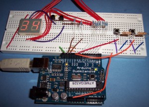
This week we modify the original circuit and sketch to include two buttons, one to control each digit of the display.
Here’s what the setup looks like:
And here’s the complete sketch:
// www.TinkerHobby.com
// Natalia Fargasch Norman
// Dual seven-segment LED Display with buttons
// Common Anode digit 1 pin 10
// Common Anode digit 2 pin 5

//       CA1 G  F  A  B
//        |  |  |  |  |      -> pins and segments they control
//   ---------    ---------
//   |   A   |    |   A   |
//  F|       |B  F|       |B
//   |---G---|    |---G---|
//  E|       |C  E|       |C
//   |   D   |    |   D   |
//   ---------    ---------
//        |  |  |  |  |      -> pins and segments they control
//        D  DP E  C CA2

// Segments that make each number when lit:
// 0 => -FEDCBA
// 1 => ----BC-
// 2 => G-ED-BA
// 3 => G--DCBA
// 4 => GF--CB-
// 5 => GF-DC-A
// 6 => GFEDC-A
// 7 => ----CBA
// 8 => GFEDCBA
// 9 => GF-DCBA

// Arduino digital pins used to light up
// corresponding segments on the LED display
#define A 3
#define B 2
#define C 6
#define D 8
#define E 7
#define F 4
#define G 5

// Pushbuttons connected to pins 9 and 10
#define BTN1 9
#define BTN2 10

// Pins driving common anodes
#define CA1 13
#define CA2 12

// Pins for A B C D E F G, in sequence
const int segs[7] = { A, B, C, D, E, F, G };

// Segments that make each number
const byte numbers[10] = { 0b1000000, 0b1111001, 0b0100100, 0b0110000, 0b0011001, 0b0010010,
0b0000010, 0b1111000, 0b0000000, 0b0010000 };

int digit1 = 0;
int digit2 = 0;

void setup() {
  pinMode(A, OUTPUT);
  pinMode(B, OUTPUT);
  pinMode(C, OUTPUT);
  pinMode(D, OUTPUT);
  pinMode(E, OUTPUT);
  pinMode(F, OUTPUT);
  pinMode(G, OUTPUT);
  pinMode(BTN1, INPUT);
  pinMode(BTN2, INPUT);
  pinMode(CA1, OUTPUT);
  pinMode(CA2, OUTPUT);
}

void loop() {

  // check button1
  int val1 = digitalRead(BTN1);
  if (val1 == HIGH) {
    digit1++;
    digit1 %= 10;
    delay(10);
  }

  // check button2
  int val2 = digitalRead(BTN2);
  if (val2 == HIGH) {
    digit2++;
    digit2 %= 10;
    delay(10);
  }

  // display number
  unsigned long startTime = millis();
  for (unsigned long elapsed=0; elapsed < 600; elapsed = millis() - startTime) {
    lightDigit1(numbers[digit1]);
    delay(5);
    lightDigit2(numbers[digit2]);
    delay(5);
  }
}

void lightDigit1(byte number) {
  digitalWrite(CA1, LOW);
  digitalWrite(CA2, HIGH);
  lightSegments(number);
}

void lightDigit2(byte number) {
  digitalWrite(CA1, HIGH);
  digitalWrite(CA2, LOW);
  lightSegments(number);
}

void lightSegments(byte number) {
  for (int i = 0; i < 7; i++) {
    int bit = bitRead(number, i);
    digitalWrite(segs[i], bit);
  }
}
Here’s a video of the Arduino 2-digit 7-segment display counter with buttons in action.
Arduino 2-Digit 7-Segment Display with Buttons | Part 4 originally appeared on Tinker Hobby on June 22, 2010.


