Posts | Comments

Planet Arduino

Archive for the ‘OLED’ Category

Back in the 486 days, it was common to see a “Turbo” button on the front panel of many PCs, which was used to toggle between the CPU’s maximum speed and a slower clock rate that was sometimes necessary for compatibility with older software. Usually an LED would light up to show you were running at this higher speed, or if you’re machine was very fancy, it might even have a numerical display that would show the current CPU frequency.

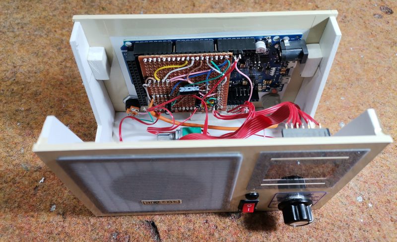
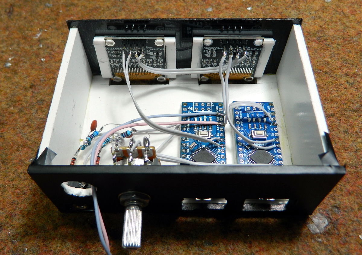
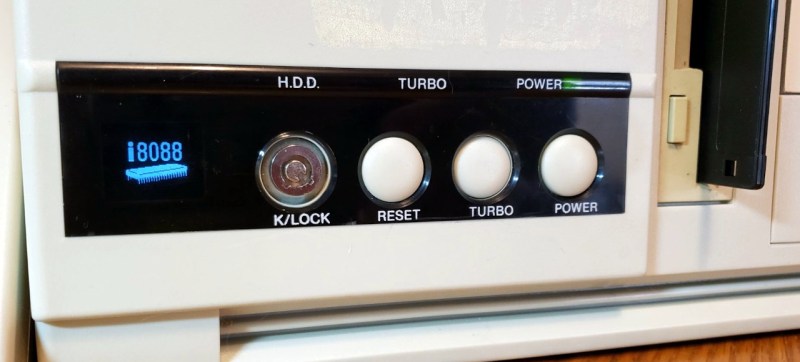
[Joshua Woehlke] wanted to add a similar display to his 486, but figured that with modern technology, he could do something a bit more interesting. Especially when he realized that the spot on his case where the two-digit LED display would have originally been mounted was the perfect size to hold a common 0.96″ SSD1306 OLED. From there it was just a matter of wiring it up to an Arduino and writing some code to display different graphics depending on the computer’s current CPU speed.

Just like the frequency indicators of yore, the Arduino doesn’t actually measure the CPU’s frequency, it’s simply reading the state of the Turbo LED on the front panel. When the LED is off the Arduino shows an image of a i8088 CPU on the screen to indicate the computer is running in compatibility mode, and when the LED is on, the screen shows the Cyrix Cx486 DX2 logo. When the button hasn’t been pressed in awhile, the display defaults to a star field screensaver.

Regular readers may recall we recently covered a similar project that used an Arduino to add a little flair to an era appropriate seven-segment LED display. We’d say there’s still a good deal of romanticism about computers having a big “TURBO” button you can smash whenever you feel the need for speed.

"The Great Resistor" color code illumination project

With surface-mount components quickly becoming the norm, even for homebrew hardware, the resistor color-code can sometimes feel a bit old-hat. However, anybody who has ever tried to identify a random through-hole resistor from a pile of assorted values will know that it’s still a handy skill to have up your sleeve. With this in mind, [j] decided to super-size the color-code with “The Great Resistor”.

Resistor color code from Wikipedia with white background
How the resistor color-code bands work

At the heart of the project is an Arduino Nano clone and a potential divider that measures the resistance of the test resistor against a known fixed value. Using the 16-bit ADC, the range of measurable values is theoretically 0 Ω to 15 MΩ, but there are some remaining issues with electrical noise that currently limit the practical range to between 100 Ω and 2 MΩ.

[j] is measuring the supply voltage to help counteract the noise, but intends to move to an oversampling/averaging method to improve the results in the next iteration.

The measured value is shown on the OLED display at the front, and in resistor color-code on an enormous symbolic resistor lit by WS2812 RGB LEDs behind.

Inside view of the great resistor showing WS2812 LEDs and baffle plates
Inside The Great Resistor, the LEDs and baffle plates make the magic work

Precision aside, the project looks very impressive and we like the way the giant resistor has been constructed. It would look great at a science show or a demonstration. We’re sure that the noise issues can be ironed out, and we’d encourage any readers with experience in this area to offer [j] some tips in the comments below. There’s a video after the break of The Great Resistor being put through its paces!

If you want to know more about the history of the resistor color code bands, then we have you covered.  Alternatively, how about reading the color code directly with computer vision?

Arduino hearing test device overview

Hearing loss is a common problem for many – especially those who may have attended too many loud concerts in their youth. [mircemk] had recently been for a hearing test, and noticed that the procedure was actually quite straightforward. Armed with this knowledge, he decided to build his own test system and document it for others to use.

audiogram showing the results of the arduino hearing test device
Resultant audiogram from the device showing each ear in a different color

By using an Arduino to produce tones of various stepped frequencies, and gradually increasing the volume until the test subject can detect the tone, it is possible to plot an audiogram of hearing threshold sensitivity.  Testing each ear individually allows a comparison between one side and the other.

[mircemk] has built a nice miniature cabinet that holds an 8×8 matrix of WS2812 addressable RGB LEDs.  A 128×64 pixel OLED display provides user instructions, and a rotary encoder with push-button serves as the user input.

Of course, this is not a calibrated professional piece of test equipment, and a lot will depend on the quality of the earpiece used.  However, as a way to check for gross hearing issues, and as an interesting experiment, it holds a lot of promise.

There is even an extension, including a Class D audio amplifier, that allows the use of bone-conduction earpieces to help narrow down the cause of hearing loss further.

There’s some more information on bone conduction here, and we’ve covered an intriguing optical stimulation cochlear implant, too.

DIy Arduino FM radio enclosure with the lid off, showing the electronics inside

Older hackers will remember that a crystal set radio receiver was often one of the first projects attempted.  Times have changed, but there’s still something magical about gathering invisible signals from the air and listening to the radio on a homemade receiver. [mircemk] has brought the idea right up to date by building an FM radio with an OLED display, controlled with a rotary encoder.

The design is fairly straightforward, based as it is on another project that [mircemk] found on a Chinese site, but the build looks very slick and would take pride of place on any hacker’s workbench. An Arduino Due forms the heart of the project, controlling a TEA5767 module, an SH1106 128×64 pixel OLED display and a rotary encoder. The sound signal is passed through an LM4811 headphone amplifier for private listening, and a PAM8403 Class D audio amplifier for the built-in loudspeaker. The enclosure is made from PVC panels, and accented with colored adhesive tape for style.

It’s easier than ever before to quickly put together projects like this by connecting pre-built modules and downloading code from the Internet, but that doesn’t mean it’s not a worthwhile way to improve your skills and make some useful devices like this one. There are so many resources available to us these days and standing on the shoulders of giants has always been a great way to see farther.

We’ve shown some other radio projects using Arduinos and the TEA5767 IC in the past, such as this one on a tidy custom PCB, and this one built into an old radio case.

Over the years we’ve seen plenty of homebrew handheld game systems that combine an AVR microcontroller, a few buttons, and an small OLED display. We’ve even seen some of them turned into commercial products, such as the Arduboy. They’re simple, cheap, and with the right software, a lot of fun. But being based on an MCU, most of them share the same limitation of only being able to hold a single game at any one time.

But not the Game Card, by [Dylan Turner]. This handheld was specifically designed so that games could be easily swapped out using physical cartridges. But rather than trying to get the system’s microcontroller to boot code from an external flash chip, the system relocates the MCU to the removable cartridge. That might seem a bit overkill, but given how cheap the ATTINY84A on each cartridge is, it’s not exactly going to break the bank.

With the microcontroller on the cartridge, the only hardware that stays behind on the Game Card is the SSD1306 128×64 OLED display, buttons, and the battery. That means the handheld is effectively non-functional unless a game is slotted in, but that could be said of most early cartridge-based game systems as well. On the other hand, it also opens up the possibility of producing cartridges with more powerful microcontrollers down the line.

Using a different microcontroller for each game is a neat hack, but it’s not the only solution to the problem. We previously saw a community effort to add expandable storage to the Arduboy in the form of a DIY cartridge, which ultimately led to the development of an official flash chip upgrade for the handheld.

Looking for a digital recreation of the classic analog volume unit (VU) meter? If you’ve got an Arduino, a few passive components, and a SSD1306 OLED, then [mircemk] might have the answer for you. As you can see in the video below, his code turns a handful of cheap parts into an attractive and functional audio display.

The project’s Hackaday.IO page explains that the idea is based on the work of [stevenart], with code adapted for the SSD1306 display and some tweaks made to the circuit. While [mircemk] says the code could be modified for stereo as long as the two displays don’t have conflicting I2C addresses, he decided to simply duplicate the whole setup for each channel to keep things simple. With as cheap as some of these parts are nowadays, it’s hard to blame him.

[mircemk] has provided source code for a couple different styles of VU indicators, the colors of which can easily be inverted depending on your tastes. He also clarifies that the jerky motion of the virtual “needle” seen in the video is due to the camera; in real-life it sweeps smoothly like the genuine article.

Much like the project that aimed to recreate authentic “steam gauges” with e-paper displays, this as an excellent technique to file away for use in the future. Compared to authentic analog gauges, these digital recreations are quicker and faster to implement, plus going this route prevents any antique hardware from going on the chopping block.

Tiny OLED displays are an absolute must-have in the modern parts bin, so what better way to show your allegiance to the maker movement than with a pair of Arduino-compatible OLED glasses? Created by Arduboy mastermind [Kevin Bates], these digital spectacles might not help you see any better — in fact, you’ll see a bit worse — but they’ll certainly make you stand out in the crowd at the next hacker con. (Whenever we can have one of those again, anyway.)

The key to this project is a pair of transparent CrystalFonts OLED displays, just like the ones [Sean Hodgins] recently used to produce his gorgeous volumetric display. In fact, [Kevin] says it was his success with these displays that inspired him to pursue his own project. With some clever PCB design, he came up with some boards that could be manufactured by OSH Park and put together with jewelry box hinges. Small flexible circuits, also from OSH Park, link the boards and allow the frames to fold up when not being worn.

The Arduglasses use the same ATmega32U4 microcontroller as the Arduboy, and with a few basic controls and a small 100 mAh rechargeable battery onboard, they can technically run anything from the open source handheld’s extensive software library. Of course, technically is the operative word here. While the hardware is capable of playing the games, [Kevin] reports that the OLED displays are too close to the wearer’s eyes to actually focus on them. That said the ability to easily create software for these glasses offers plenty of opportunity for memes, as we see in the video below.

For reasons that are probably obvious, [Kevin] considers the Arduglasses an experiment and isn’t looking to turn them into a commercial product or kit. But if there’s interest, he’s willing to put the design files up on GitHub for anyone who wants to add a pair of Arduino glasses to their cyberpunk wardrobe.

One of the selling points of the Arduboy is how slim [Kevin Bates] was able to get the Arduino-compatible game system, which is perhaps less surprising when you realize that it originally started out as a design for an electronic business card. But compared to the recently unveiled Nano version, it might as well be the old school “brick” Game Boy.

Now to be clear, [Kevin] isn’t looking to put these into official production. Though it does sound like the bare PCBs might be going up for sale in the near future. This was simply an experiment to see how far he could shrink the core Arduboy hardware while still keeping it not only playable but also code-compatible with the full-size version. While “playable” might be a tad subjective in this case, the video after the break clearly demonstrates that it’s fully functional.

Inside the 3D printed case is the same ATmega32U4 that powers the Arduboy, a 64×32 0.49″ OLED display, and a tiny 25 mAh pouch battery. There’s even a miniature piezo speaker for the bleeps and bloops. All of the pinouts have remained the same so existing code can be moved right over, though the screen is now connected over I2C. [Kevin] has released the schematics for the board in keeping with the general open nature of the Arduboy project, though for now he’s decided to hold onto the board files until it’s clear whether or not there’s a commercial future for the Nano.

We’ve seen attempts to shrink the Arduboy down before, most notably down to the point it could fit inside of a Dreamcast Visual Memory Unit, but the Nano certainly raises (or is that lowers?) the bar considerably.

Sure, [Ty Palowski] could have just hung a tennis ball from the ceiling, but that would mean getting on a ladder, testing the studfinder on himself before locating a ceiling joist, and so on. Bo-ring. Now that he finally has a garage, he’s not going to fill it with junk, no! He’s going to park a big ol’ Jeep in it. Backwards.

The previous owner was kind enough to leave a workbench in the rear of the garage, which [Ty] has already made his own. To make sure that he never hits the workbench while backing into the garage, [Ty] made an adorable stoplight to help gauge the distance to it. Green mean’s he’s good, yellow means he should be braking, and red of course means stop in the name of power tools.

Inside the light is an Arduino Nano, which reads from the ultrasonic sensor mounted underneath the enclosure and lights up the appropriate LED depending on the car’s distance. All [Ty] has to do is set the distance that makes the red light come on, which he can do with the rotary encoder on the side and confirm on the OLED. The distance for yellow and green are automatically set from red — the yellow range begins 24″ past red, and green is another 48″ past yellow. Floor it past the break to watch the build video.

The humble North American traffic signal is widely recognized, so it’s a good approach for all kinds of applications. Teach your children well: start them young with a visual indicator of when it’s okay to get out of bed in the morning.


  • Newsletter

    Sign up for the PlanetArduino Newsletter, which delivers the most popular articles via e-mail to your inbox every week. Just fill in the information below and submit.

  • Like Us on Facebook