Posts | Comments

Planet Arduino

Archive for the ‘spinning night light’ Category

Jul
27

Arduino RGB LED Control for the Spinning Night Light | Part 4

arduino, light, Ohm's law, project, resistor, RGB LED, sketch, spinning night light Comments Off on Arduino RGB LED Control for the Spinning Night Light | Part 4 

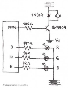
When looking at the parts list for the Arduino RGB LED spinning night light you must have noticed that current limiting resistors of different values were used for the Red and the Green/Blue pins of the RGB LED. That is due to them having different forward voltage ratings. You can find complete specs for the LED in the datasheet (when buying an electronic component you will have the option to download its datasheet, or the relevant information will be provided by the vendor).

We use Ohm’s Law to calculate current limiting resistor values:

Forward voltage ratings:

RED: 2.1V
GREEN: 3.3V
BLUE: 3.3V

Current:

I = 20mA

Supply voltage:

V = 5V

Ohm’s Law:

I = V/R => R = V/I

So for Red:

(5 – 2.1)/0.02 => R = 145 Ohm

For Green/Blue:

(5 – 3.3)/0.02 => R = 85 Ohm
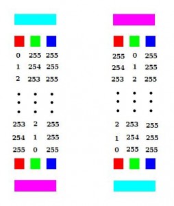
color fading for the RGB LED night lightAs for the Arduino sketch, I chose to have the lamp fade between two colors, aqua (#00FFFF) and magenta (#FF00FF). For that I kept the Blue value at 255 and varied the Green and Red values between 0-255 to achieve the desired colors, as shown in the diagram:
(You can pick your favorite colors, cycle through the entire spectrum, or go psychedelic and show random colors with random delays)

// fade from aqua to magenta
  for (int i = 0; i < 256; i++) {
    analogWrite(RED, 255-i);
    analogWrite(GREEN, i);
    analogWrite(BLUE, 0);
    delay(50);
  }

  // fade from magenta to aqua
  for (int i = 0; i < 256; i++) {
    analogWrite(RED, i);
    analogWrite(GREEN, 255-i);
    analogWrite(BLUE, 0);
    delay(50);
  }

Here’s the full sketch for the night light.

Arduino RGB LED Control for the Spinning Night Light | Part 4 originally appeared on Tinker Hobby on July 27, 2010.

Jul
20

Arduino Motor Control for the Spinning Night Light | Part 3

arduino, circuit, diode, motor, project, spinning night light, transistor Comments Off on Arduino Motor Control for the Spinning Night Light | Part 3 

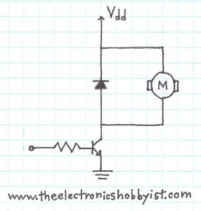
Simple motor controlMost motor control applications can be accomplished with a simple single-transistor circuit. This type of circuit controls the basic operation of turning the motor on and off, and allows very fast switching of the motor, which makes it possible to control the speed of the motor using pulse width modulation (PWM).

The basic problem with this circuit is that the direction of the motor cannot be reversed. For our simple application in this RGB LED night light, spinning the motor in one direction is enough. In the future we will use motors in applications which require us to reverse the direction as well, and for that we will be using the type of motor control circuit called H-bridge circuit.

Note that a diode has been used in this circuit. The core of all types of motors is the inductor (or coil). When the amount of current (which can be moderate to high) passing through the inductor is changed, it produces large voltage spikes (“kickback” ) .

The diode used in motor control circuits is called a kickback diode and its purpose is to absorb the voltage that is produced when the transistor is turned on and off. When you are developing motor control applications using a bipolar transistor you should always put in the kickback diode in order to protect the other parts of your circuit.

Here’s the sketch for the spinning night light.

Arduino Motor Control for the Spinning Night Light | Part 3 originally appeared on Tinker Hobby on July 20, 2010.

Jul
13

Arduino RGB LED Spinning Night Light: Assembly | Part 2

arduino, circuit, DC motor, project, RGB LED, soldering, spinning night light Comments Off on Arduino RGB LED Spinning Night Light: Assembly | Part 2 

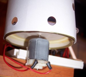
  1. Arduino RGB LED night light schematicSolder wires to motor terminals and cover with heat-shrink tubing
  2. Using a knife or sharp scissors, puncture a small hole (to fit the motor shaft snugly) on the center of the jar lid
  3. Solder motor shaft to jar lid (if necessary use hot glue or super glue, as some surfaces won’t “catch” the solder easily)
  4. Solder the RGB LED leads to long wires and cover the connections with heat-shrink tubing
  5. Build the circuit on the mini breadboard using the schematic as your guide
  6. Prepare the paper diffuser (use a hole puncher and punch a few holes to allow some light to shine through) and tape it around the jar lid using mounting tape

  7. motor leads

  8. Mount the motor to the side of the breadboard using mounting tape
  9. Tie the LED wires together and secure the wire bundle using a stick as prop (I used a lollipop stick in one of the holes on the breadboard); split the stick tip shaping it as a “Y” to help secure the LED wires in place(show finished picture)

Check the previous post if you need to see the sketch for the Arduino RGB LED night light again.

Arduino RGB LED Spinning Night Light: Assembly | Part 2 originally appeared on Tinker Hobby on July 13, 2010.

Jul
06

Arduino RGB LED Spinning Night Light | Part 1

arduino, DC motor, project, RGB LED, sketch, spinning night light, video Comments Off on Arduino RGB LED Spinning Night Light | Part 1 

Arduino RGB LED Night LightThis month’s project uses the Arduino to control a motor and an RGB LED to create an aquarium style spinning night light.

The initial idea was to recycle empty toilet paper tubes to serve as the lampshade, but it turns out the project looks much more attractive and colorful using white paper. (I haven’t given up on the idea of finding a use for the empty tubes, though. Suggestions are welcome.)

A simple DC Motor is used to spin the lamp structure, and a jar lid serves as the base. There is (a lot of) room for improvement in the design of the lamp, but I’m a computer scientist and wanna-be crafter at best.

I intend to revisit these projects in the future, and make them stand alone using smaller Arduino boards and sporting a nicer finish (something worthy of showing guests). For now the purpose of these projects is solely educational (in a microcontroller programming way, not hand crafting).

In the upcoming posts we will explore the assembly of the night light, as well as the circuit and Arduino sketch that make the project work.

Parts list:

I have recorded a short video of the Arduino RGB LED Spinning Night Light in action.

And here is the Arduino sketch:

// www.TinkerHobby.com
// Natalia Fargasch Norman
// RGB LED night light using Arduino

// Arduino pins used for motor and LEDs
#define MOTOR 3
#define RED 9
#define GREEN 10
#define BLUE 11

// pins for motor and LEDs are outputs
void setup() {
  pinMode(MOTOR, OUTPUT);
  pinMode(RED, OUTPUT);
  pinMode(GREEN, OUTPUT);
  pinMode(BLUE, OUTPUT);
}

void loop() {
  // set motor speed, between 0 and 255
  analogWrite(MOTOR, 69);

  // fade from aqua to magenta
  for (int i = 0; i < 256; i++) {
    analogWrite(RED, 255-i);
    analogWrite(GREEN, i);
    analogWrite(BLUE, 0);
    delay(50);
  }

  // fade from magenta to aqua
  for (int i = 0; i < 256; i++) {
    analogWrite(RED, i);
    analogWrite(GREEN, 255-i);
    analogWrite(BLUE, 0);
    delay(50);
  }

}

Arduino RGB LED Spinning Night Light | Part 1 originally appeared on Tinker Hobby on July 6, 2010.


  • Newsletter

    Sign up for the PlanetArduino Newsletter, which delivers the most popular articles via e-mail to your inbox every week. Just fill in the information below and submit.

  • Like Us on Facebook