Timepieces are cool no matter how simplistic or granular they are. Sometimes its nice not to know exactly what time it is down to the second, and most of the really beautiful clocks are simple as can be. If you didn’t know this was a clock, it would still be fascinating to watch the bearings race around the face.
This clock takes design cues from the Story clock, a visual revolution in counting down time which uses magnetic levitation to move a single bearing around the face exactly once over a duration of any length as set by the user. As a clock, it’s not very useful, so there’s a digital readout that still doesn’t justify the $800 price tag.
[tomatoskins] designed a DIY version that’s far more elegant. It has two ball bearings that move around the surface against hidden magnets — an hour ball and a minute ball. Inside there’s a pair of 3D-printed ring gears that are each driven by a stepper motor and controlled with an Arduino Nano and a real-time clock module. The body is made of plywood reclaimed from a bed frame, and [tomatoskins] added a walnut veneer for timeless class.
In addition to the code, STLs, and CAD files that birthed the STLs, [tomatoskins] has a juicy 3D-printing tip to offer. The gears had to be printed in interlocked pieces, but these seams can be sealed with a solution of acetone and plastic from supports and failed prints.
[Sofia] spent a lot of time looking around for the perfect LEGO clock. Eventually, she realized that the perfect LEGO clock is, of course, the one you build yourself. So if you find yourself staring at the same old boring clock, contemplating time and the meaning of time itself, why not spend some time making a new timepiece?
You probably already had the LEGO out (no judgment here). This build doesn’t take a whole lot of building blocks — just a microcontroller, a real-time clock module, some LED matrices to display the digits, shift registers if they’re not already built into the matrices, and a pair of buttons for control. [Sofia] used an Arduino Nano, but any microcontroller with enough I/O ought to work. Everybody needs a colorful new way to block out their time.
We love the way this clock looks, especially the transparent panels in front of the LED panels. Given the countless custom pieces out there from all the special sets over the years, we bet you could come up with some really interesting builds.
In this tutorial we look at how to use the neat LED Real Time Clock Temperature Sensor Shield for Arduino from PMD Way. That’s a bit of a mouthful, however the shield does offer the following:
four digit, seven-segment LED display
DS1307 real-time clock IC
three buttons
four LEDs
a active buzzer
a light-dependent resistor (LDR)
and a thermistor for measuring ambient temperature
The shield also arrives fully-assembled , so you can just plug it into your Arduino Uno or compatible board. Neat, beginners will love that. So let’s get started, by showing how each function can be used – then some example projects. In no particular order…
The buzzer
A high-pitched active buzzer is connected to digital pin D6 – which can be turned on and off with a simple digitalWrite() function. So let’s do that now, for example:
voidsetup(){// buzzer on digital pin 6pinMode(6,OUTPUT);}// the loop function runs over and over again forevervoidloop(){digitalWrite(6,HIGH);// turn the buzzer on (HIGH is the voltage level)delay(1000);// wait for a seconddigitalWrite(6,LOW);// turn the buzzer off by making the voltage LOWdelay(1000);// wait for a second}
If there is a white sticker over your buzzer, remove it before uploading the sketch. Now for a quick video demonstration. Turn down your volume before playback.
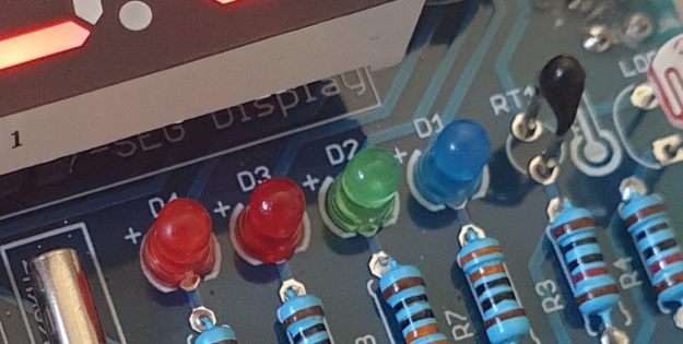
The LEDs
Our shield has four LEDs, as shown below:
They’re labelled D1 through to D4, with D1 on the right-hand side. They are wired to digital outputs D2, D3, D4 and D5 respectively. Again, they can be used with digitalWrite() – so let’s do that now with a quick demonstration of some blinky goodness. Our sketch turns the LEDs on and off in sequential order. You can change the delay by altering the variable x:
voidsetup(){// initialize digital pin LED_BUILTIN as an output.pinMode(2,OUTPUT);// LED 1pinMode(3,OUTPUT);// LED 2pinMode(4,OUTPUT);// LED 3pinMode(5,OUTPUT);// LED 4}intx=200;voidloop(){digitalWrite(2,HIGH);// turn on LED1delay(x);digitalWrite(2,LOW);// turn off LED1. Process repeats for the other three LEDsdigitalWrite(3,HIGH);delay(x);digitalWrite(3,LOW);digitalWrite(4,HIGH);delay(x);digitalWrite(4,LOW);digitalWrite(5,HIGH);delay(x);digitalWrite(5,LOW);}
And in action:
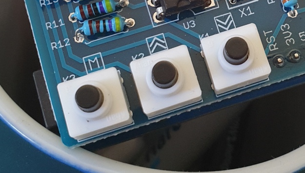
The Buttons
It is now time to pay attention to the three large buttons on the bottom-left of the shield. They look imposing however are just normal buttons, and from right-to-left are connected to digital pins D9, D10 and D11:
They are, however, wired without external pull-up or pull-down resistors so when initialising them in your Arduino sketch you need to activate the digital input’s internal pull-up resistor inside the microcontroller using:
pinMode(pin, INPUT_PULLUP);
Due to this, buttons are by default HIGH when not pressed. So when you press a button, they return LOW. The following sketch demonstrates the use of the buttons by lighting LEDs when pressed:
voidsetup(){// initalise digital pins for LEDs as outputspinMode(2,OUTPUT);// LED 1pinMode(3,OUTPUT);// LED 2pinMode(4,OUTPUT);// LED 3// initalise digital pins for buttons as inputs// and initialise internal pullupspinMode(9,INPUT_PULLUP);// button K1pinMode(10,INPUT_PULLUP);// button K2pinMode(11,INPUT_PULLUP);// button K3}voidloop(){if(digitalRead(9)==LOW){digitalWrite(2,HIGH);delay(10);digitalWrite(2,LOW);}if(digitalRead(10)==LOW){digitalWrite(3,HIGH);delay(10);digitalWrite(3,LOW);}if(digitalRead(11)==LOW){digitalWrite(4,HIGH);delay(10);digitalWrite(4,LOW);}}
You can see these in action via the following video:
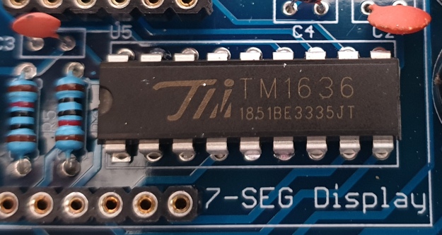
The Numerical LED Display
Our shield has a nice red four-digit, seven-segment LED clock display. We call it a clock display as there are colon LEDs between the second and third digit, just as a digital clock would usually have:
The TM1636 itself is an interesting part, so we’ll explain that in a separate tutorial in the near future. For now, back to the shield.
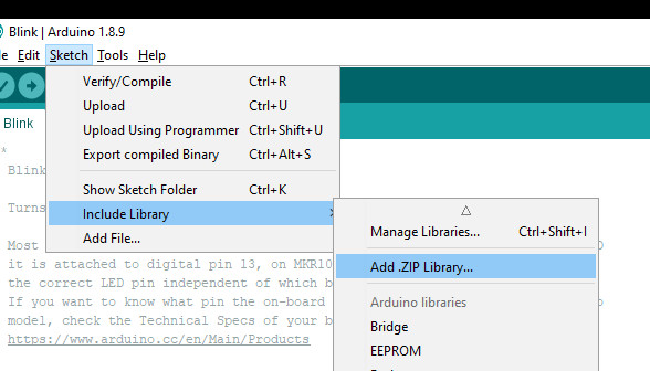
To control the LED display we need to install an Arduino library. In fact the shield needs four, so you can install them all at once now. Download the .zip file from here. Then expand that into your local download directory – it contains four library folders. You can then install them one at a time using the Arduino IDE’s Sketch > Include library > Add .zip library… command:
The supplied library offers five functions used to control the display.
.num(x);
…this displays a positive integer (whole number) between 0 and 9999.
.display(p,d);
… this shows a digit d in location p (locations from left to right are 3, 2, 1, 0)
.time(h,m)
… this is used to display time data (hours, minutes) easily. h is hours, m is minutes
.pointOn();
.pointOff();
… these turn the colon on … and off. And finally:
.clear();
… which clears the display to all off. At the start of the sketch, we need to use the library and initiate the instance of the display by inserting the following lines:
#include <TTSDisplay.h>
TTSDisplay rtcshield;
Don’t panic – the following sketch demonstrates the five functions described above:
#include<TTSDisplay.h>TTSDisplayrtcshield;inta=0;intb=0;voidsetup(){}voidloop(){// display some numbersfor(a=4921;a<5101;a++){rtcshield.num(a);delay(10);}// clear displayrtcshield.clear();// display individual digitsfor(a=3;a>=0;--a){rtcshield.display(a,a);delay(1000);rtcshield.clear();}for(a=3;a>=0;--a){rtcshield.display(a,a);delay(1000);rtcshield.clear();}// turn the colon and offfor(a=0;a<5;a++){rtcshield.pointOn();delay(500);rtcshield.pointOff();delay(500);}// demo the time display functionrtcshield.pointOn();rtcshield.time(11,57);delay(1000);rtcshield.time(11,58);delay(1000);rtcshield.time(11,59);delay(1000);rtcshield.time(12,00);delay(1000);}
And you can see it in action through the video below:
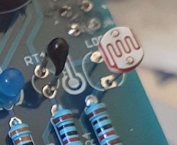
The LDR (Light Dependent Resistor)
LDRs are useful for giving basic light level measurements, and our shield has one connected to analog input pin A1. It’s the two-legged item with the squiggle on top as shown below:
The resistance of LDRs change with light levels – the greater the light, the less the resistance. Thus by measuring the voltage of a current through the LDR with an analog input pin – you can get a numerical value proportional to the ambient light level. And that’s just what the following sketch does:
#include<TTSDisplay.h>TTSDisplayrtcshield;inta=0;voidsetup(){}voidloop(){// read value of analog inputa=analogRead(A1);// show value on displayrtcshield.num(a);delay(100);}
The Thermistor
A thermistor is a resistor whose resistance is relative to the ambient temperature. As the temperature increases, their resistance decreases. It’s the black part to the left of the LDR in the image below:
We can use this relationship between temperature and resistance to determine the ambient temperature. To keep things simple we won’t go into the theory – instead, just show you how to get a reading.
The thermistor circuit on our shield has the output connected to analog input zero, and we can use the library installed earlier to take care of the mathematics. Which just leaves us with the functions.
At the start of the sketch, we need to use the library and initiate the instance of the thermistor by inserting the following lines:
#include <TTSTemp.h>
TTSTemp temp;
… then use the following which returns a positive integer containing the temperature (so no freezing cold environments):
.get();
For our example, we’ll get the temperature and show it on the numerical display:
And our thermometer in action. No video this time… a nice 24 degrees C in the office:
The Real-Time Clock
Our shield is fitted with a DS1307 real-time clock IC circuit and backup battery holder. If you insert a CR1220 battery, the RTC will remember the settings even if you remove the shield from the Arduino or if there’s a power blackout, board reset etc:
The DS1307 is incredibly popular and used in many projects and found on many inexpensive breakout boards. We have a separate tutorial on how to use the DS1307, so instead of repeating ourselves – please visit our specific DS1307 Arduino tutorial, then return when finished.
Where to from here?
We can image there are many practical uses for this shield, which will not only improve your Arduino coding skills but also have some useful applications. An example is given below, that you can use for learning or fun.
Temperature Alarm
This projects turns the shield into a temperature monitor – you can select a lower and upper temperature, and if the temperature goes outside that range the buzzer can sound until you press it.
Here’s the sketch:
#include<TTSDisplay.h>#include<TTSTemp.h>TTSTemptemp;TTSDisplayrtcshield;booleanalarmOnOff=false;inthighTemp=40;intlowTemp=10;intcurrentTemp;voidLEDsoff(){// function to turn all alarm high/low LEDs offdigitalWrite(2,LOW);digitalWrite(4,LOW);}voidsetup(){// initalise digital pins for LEDs and buzzer as outputspinMode(2,OUTPUT);// LED 1pinMode(3,OUTPUT);// LED 2pinMode(4,OUTPUT);// LED 3pinMode(5,OUTPUT);// LED 4pinMode(6,OUTPUT);// buzzer// initalise digital pins for buttons as inputs// and initialise internal pullupspinMode(9,INPUT_PULLUP);// button K1pinMode(10,INPUT_PULLUP);// button K2pinMode(11,INPUT_PULLUP);// button K3}voidloop(){// get current temperaturecurrentTemp=temp.get();// if current temperature is within set limts// show temperature on displayif(currentTemp>=lowTemp||currentTemp<=highTemp)// if ambient temperature is less than high boundary// OR if ambient temperature is grater than low boundary// all is well{LEDsoff();// turn off LEDsrtcshield.num(currentTemp);}// if current temperature is above set high bounday, show red LED and// show temperature on display// turn on buzzer if alarm is set to on (button K3)if(currentTemp>highTemp){LEDsoff();// turn off LEDsdigitalWrite(4,HIGH);// turn on red LEDrtcshield.num(currentTemp);if(alarmOnOff==true){digitalWrite(6,HIGH);// buzzer on }}}// if current temperature is below set lower boundary, show blue LED and// show temperature on display// turn on buzzer if alarm is set to on (button K3)if(currentTemp<lowTemp){LEDsoff();// turn off LEDsdigitalWrite(2,HIGH);// turn on blue LEDrtcshield.num(currentTemp);if(alarmOnOff==true){digitalWrite(6,HIGH);// buzzer on }}}// --------turn alarm on or off-----------------------------------------------------if(digitalRead(11)==LOW)// turn alarm on or off{alarmOnOff=!alarmOnOff;if(alarmOnOff==0){digitalWrite(6,LOW);// turn off buzzerdigitalWrite(5,LOW);// turn off alarm on LED}// if alarm is set to on, turn LED on to indicate thisif(alarmOnOff==1){digitalWrite(5,HIGH);}delay(300);// software debounce}// --------set low temperature------------------------------------------------------if(digitalRead(10)==LOW)// set low temperature. If temp falls below this value, activate alarm{// clear display and turn on blue LED to indicate user is setting lower boundaryrtcshield.clear();digitalWrite(2,HIGH);// turn on blue LEDrtcshield.num(lowTemp);// user can press buttons K2 and K1 to decrease/increase lower boundary.// once user presses button K3, lower boundary is locked in and unit goes// back to normal statewhile(digitalRead(11)!=LOW)// repeat the following code until the user presses button K3{if(digitalRead(10)==LOW)// if button K2 pressed{--lowTemp;// subtract one from lower boundary// display new value. If this falls below zero, won't display. You can add checks for this yourself :)rtcshield.num(lowTemp);}if(digitalRead(9)==LOW)// if button K3 pressed{lowTemp++;// add one to lower boundary// display new value. If this exceeds 9999, won't display. You can add checks for this yourself :)rtcshield.num(lowTemp);}delay(300);// for switch debounce}digitalWrite(2,LOW);// turn off blue LED}// --------set high temperature-----------------------------------------------------if(digitalRead(9)==LOW)// set high temperature. If temp exceeds this value, activate alarm{// clear display and turn on red LED to indicate user is setting lower boundaryrtcshield.clear();digitalWrite(4,HIGH);// turn on red LEDrtcshield.num(highTemp);// user can press buttons K2 and K1 to decrease/increase upper boundary.// once user presses button K3, upper boundary is locked in and unit goes// back to normal statewhile(digitalRead(11)!=LOW)// repeat the following code until the user presses button K3{if(digitalRead(10)==LOW)// if button K2 pressed{--highTemp;// subtract one from upper boundary// display new value. If this falls below zero, won't display. You can add checks for this yourself :)rtcshield.num(highTemp);}if(digitalRead(9)==LOW)// if button K3 pressed{highTemp++;// add one to upper boundary// display new value. If this exceeds 9999, won't display. You can add checks for this yourself :)rtcshield.num(highTemp);}delay(300);// for switch debounce}digitalWrite(4,LOW);// turn off red LED}}
Operating instructions:
To set lower temperature, – press button K2. Blue LED turns on. Use buttons K2 and K1 to select temperature, then press K3 to lock it in. Blue LED turns off.
To set upper temperature – press button K1. Red LED turns on. Use buttons K2 and K1 to select temperature, then press K3 to lock it in. Red LED turns off.
If temperature drops below lower or exceeds upper temperature, the blue or red LED will come on.
You can have the buzzer sound when the alarm activates – to do this, press K3. When the buzzer mode is on, LED D4 will be on. You can turn buzzer off after it activates by pressing K3.
Display will show ambient temperature during normal operation.
You can see this in action via the video below:
Conclusion
This is a fun and useful shield – especially for beginners. It offers a lot of fun and options without any difficult coding or soldering – it’s easy to find success with the shield and increase your motivation to learn more and make more.
You can be serious with a clock, or annoy people with the buzzer. And at the time of writing you can have one for US$14.95, delivered. So go forth and create something.
A little research has shown that this shield was based from a product by Seeed, who discontinued it from sale. I’d like to thank them for the library.
This post brought to you by pmdway.com – everything for makers and electronics enthusiasts, with free delivery worldwide.
To keep up to date with new posts at tronixstuff.com, please subscribe to the mailing list in the box on the right, or follow us on twitter @tronixstuff.
There’s no shortage of clock projects, but [niq_ro] has his own take using a vacuum fluorescent display (VFD), and Arduino, and a pair of MAX6921 ICs. Those chips are made to drive a VFD, and the use of two of the ICs required a bit of work. The Arduino is not a great time keeper, so the clock also uses a DS3231 clock module and a humidity and temperature sensor.
The clock is in Romanian, although there are some options for different text. You can find the code on GitHub and can see the result in the video below.
VFDs are often used in places where a display is meant to be read outdoors. It uses cathodoluminescence to actually generate light. The process is similar to a CRT, but at lower voltages. The tubes have a phosphor-coated anode and the cathode bombards it with electrons, making the phosphor glow. VFDs are available in different colors.
Solenoids (a type of electromagnet) are at the heart of pinball machines, and at one time, many other machines. They work by inducing a magnetic field using a coil of copper wire. This makes them ideal for pushing or pulling mechanical things fast and with force. They have become unnecessary […]
We’re surprised we haven’t seen this kind of clock before, or maybe we have, but forgot about it in the dark filing cabinets of our minds. The above picture of [danjhamer’s] Matrix Clock doesn’t quite do it justice, because this is a clock that doesn’t just tick away and idly update the minutes/hours.
Instead, a familiar Matrix-esque rain animation swoops in from above, exchanging old numbers for new. For the most part, the build is what you would expect: a 16×8 LED Matrix display driven by a TLC5920 LED driver, with an Arduino that uses a DS1307 RTC (real-time clock) with a coin cell battery to keep track of time when not powered through USB. [danjhamer] has also created a 3D-printed enclosure as well as added a piezo speaker to allow the clock to chime off customizable musical alarms.
You can find schematics and other details on his Hackaday.io project page, but first, swing down below the jump to see more of the clock’s simple but awesome animations.
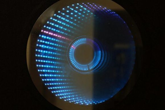
We don’t think we’ve seen an Infinity Mirror Clock before, but we love this new twist on an old favorite. Different colors distinguish between seconds, minutes and hours, and an additional IR sensor detects when someone is directly in front of the clock and switches the LEDs off, allowing it to be used as a normal mirror. This build is the work of [Dushyant Ahuja], who is no stranger to hacking together clocks out of LEDs. You can tell how much progress he’s made with the mirror clock by taking a glance at his first project, which is an impressive creation held together by jumbles of wire and some glue.
[Dushyant] has stepped up his game for his new clock, attaching an LED strip along the inside of a circular frame to fashion the infinity mirror effect. The lights receive a signal from an attached homemade Arduino board, which is also connected to a real-time clock (RTC) module to keep time and to a Bluetooth module, which allows [Dushyant] to program the clock wirelessly rather than having to drag out some cords if the clock ever needs an adjustment.
Stick around after the jump for a quick demonstration video. The lights are dazzling to watch; [Dushyant] inserted a stainless steel plate at the center of the circle to reflect the outer rim of LEDs. After a quick rainbow effect, it looks like the mirror enters clock mode. See if you can figure out what time it is. For a more step-by-step overview of this project, swing by his Instructables page.
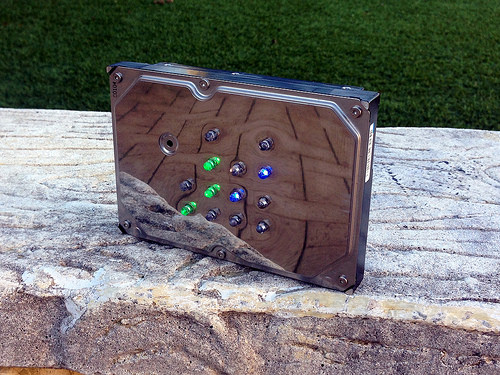
[Aaron] has been wanting to build his own binary desk clock for a while now. This was his first clock project, so he decided to keep it simple and have it simply display the time. No alarms, bells, or whistles.
The electronics are relatively simple. [Aaron] decided to use on of the ATMega328 chips he had lying around that already had the Arduino boot loader burned into them. He first built his own Arduino board on a breadboard and then re-built it on a piece of protoboard as a more permanent solution. The Arduino gets the time from a real-time clock (RTC) module and then displays it using an array of blue and green LED’s. The whole thing is powered using a spare 9V wall wort power supply.
[Aaron] chose to use the DS1307 RTC module to keep time. This will ensure that the time is kept accurately over along period of time. The RTC module has its own built-in battery, which means that if [Aaron's] clock should ever lose power the clock will still remember the time. The RTC battery can theoretically last for up to ten years.
[Aaron] got creative for his clock enclosure, upcycling an old hard drive. All of the hard drive guts were removed and replaced with his own electronics. The front cover had 13 holes drilled out for the LED’s. There are six green LED’s to display the hour, and seven blue LED’s for the minute. The LED’s were wired up as common cathode. Since the hard drive cover is conductive, [Aaron] covered both sides of his circuit board with electrical tape and hot glue to prevent any short circuits. The end result is an elegant binary clock that any geek would be proud of.
BO.Duino is an Arduino compatible board based on ATmega328 ATMEL’s mcu. This board features many peripherals usually externally connected on a breadboard or prototyping board such as sensors, SD card etc. Peripherals included are:
- A real-time clock
- AT24 series external memory chip
- MicroSD card adaptor (SPI)
- RGB LED
- A potentiometer on analog input
- Connector for DS18b20 or DHt11 series sensors
[Stewart] tipped us about his very nice project: pokewithastick. It is an Arduino compatible board (hardware, not footprint) based on the ATMEGA1284P which can be programmed to collect and post data to internet logging sites such as Thingspeak or Xively.
As you can see in the picture above, it has a small 50x37mm footprint (roughly 2″x1.5″). The pokewithastick is composed of an Wiz820 Ethernet module, a micro-SD card slot, 2 serial ports, one battery backed Real Time Clock (RTC), one radio connector (for the usual nRF24L01 2.4GHz radio), one power & user LED and finally a reset button. There are two power rails on the board which can be split (5v + 3.3V) or combined (3.3v only) which may allow you to connect Arduino shields to it. You can program the board using the standard 6-pin header or via a serial programmer if an appropriate (Arduino) bootloader is installed.
The project is open hardware, has been designed using Kicad and all the files can be downloaded as a zip file.
Planet Arduino is, or at the moment is wishing to become, an aggregation of public weblogs from around the world written by people who develop, play, think on Arduino platform and his son. The opinions expressed in those weblogs and hence this aggregation are those of the original authors. Entries on this page are owned by their authors. We do not edit, endorse or vouch for the contents of individual posts. For more information about Arduino please visit www.arduino.cc
You are currently browsing the archives for the Real-time clock category.

 This clock takes design cues from the Story clock, a visual revolution in counting down time which uses magnetic levitation to move a single bearing around the face exactly once over a duration of any length as set by the user. As a clock, it’s not very useful, so there’s a digital readout that still doesn’t justify the $800 price tag.