[nickatredbox] has a passion in building planes. Here the details of another work:
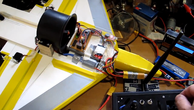
Yellow Jet 758 Grams with remaining Coroplast 2 X 7.4 V 1300 mAh batteries Arduino Nano RX Xbee with antenna, servos and misc hardware. Chamfered the top on the leading edges. All control surfaces cut and hinged. ESC mounted
Elevator mechanism for EDF jet carbon rod and ballpoint pen ink reservoir seems quite stiff with low backlash
See the video here http://www.youtube.com/watch?v=_Z9wEU6c1F0&hd=1
This plane flew pretty poorly unfortunately, but the controller worked well the EDF lacked thrust
Another interesting project by [nickatredbox], you can find this and all others on the [website].
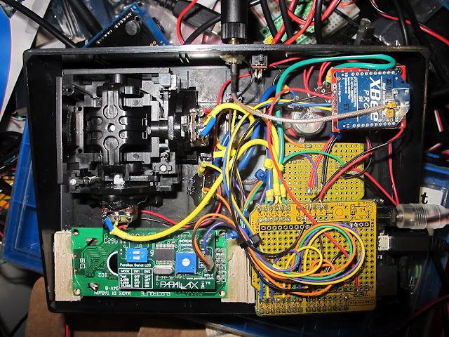
This project is a plane with the Arduino Xbee remote control working on its maiden flight. It worked well no technical issues, very happy with the results
Building the controller was a very interesting curve, learned a lot of practical usage solutions to problems and ended up with a simple piece of code which is always good in my experience, keep it simple but not to simple.
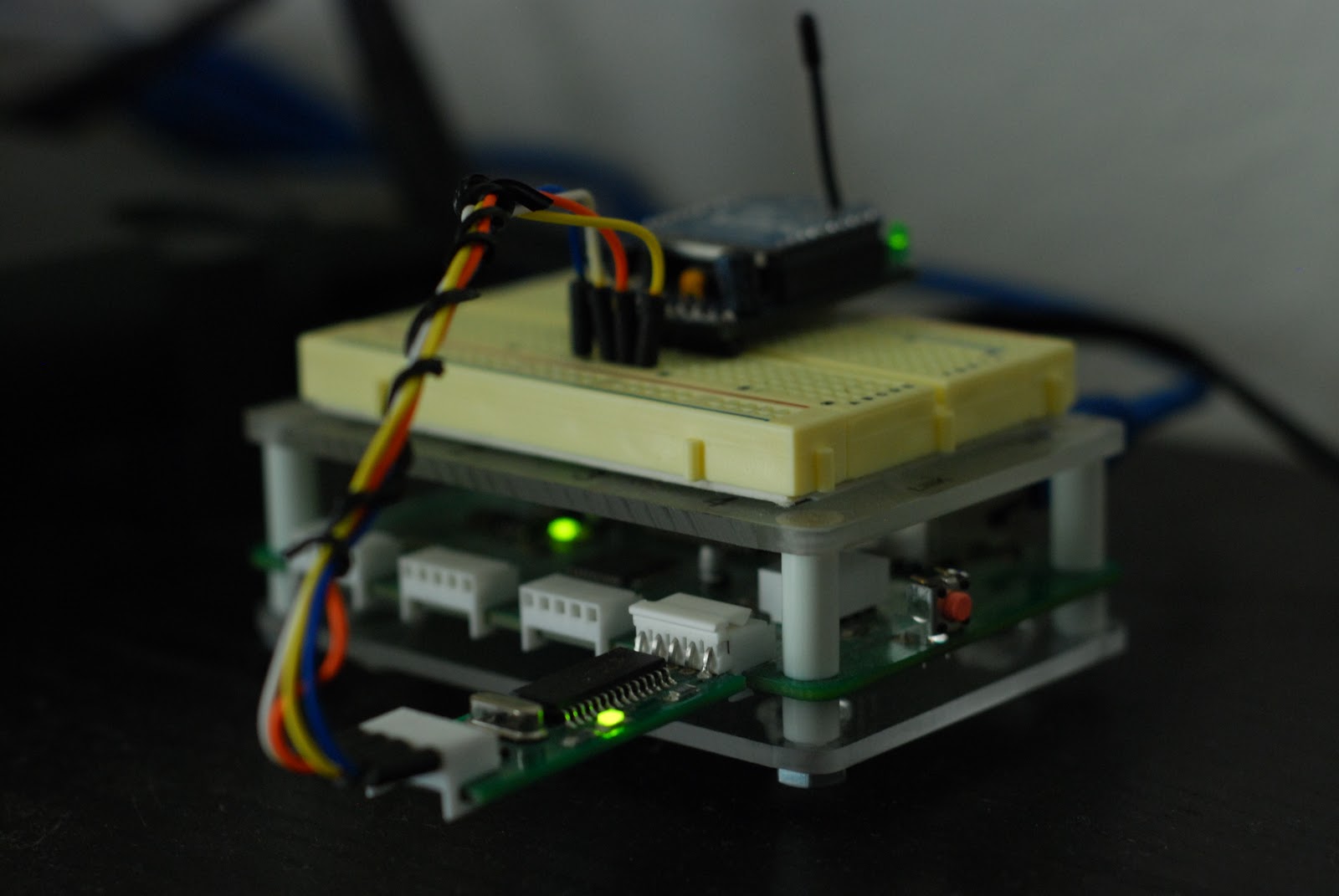
[nickatredbox] has sent this interesting project with Arduino involving wireless comunication. The fun comes when you have to decide to buy something already done or DIY.
I wanted a remote control system of my own design for may various RC model projects planes and boats. I set about researching the options and and Xbee with / Arduino solution poped out as a viable option, having failed performance testing using both WiFi and TinyCLR. The other feature I get as the Xbee is a transceiver is real-time telemetery. I’m sure I could buy this functionality from HobbyKing but where is the fun in that.
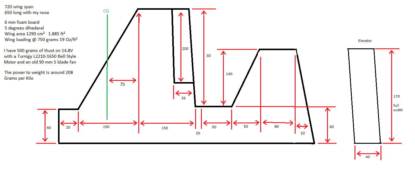
Yellow Jet 758 Grams with remaining Coroplast 2 X 7.4 V 1300 mAh batteries Arduino Nano RX Xbee with antenna, servos and misc hardware. Chamfered the top on the leading edges. All control surfaces cut and hinged. ESC mounted Lots of Jets http://www.rcgroups.com/forums/thumbgallery.php?do=showattach&u=151599&page=5 Space 1 Jet builder On RCgroups http://www.rcgroups.com/forums/member.php?u=151599 On 14.8 Volts its pushing almost 500 Grams, not so bad thrust mapping is as follows. 100 Grams 1.9 A 27.6 Watts 156 Grams 3.0 A 42.9 Watts 197 Grams 3.9 A 55.1 Watts 257 Grams 5.5 A 76.0 Watts 296 Grams 6.7 A 90.9 Watts 340 Grams 7.9 A 105.5 Watts 432 Grams 10.7 A 138.1 Watts 492 Grams 12.5 A 155.7 Watts
In this article we examine the Seeedstudio ”Bluetooth Bee“ modules and how they can be used in a simple way in conjunction with Android devices to control the Arduino world. Here is an example of a Bluetooth Bee:
For the curious, the hardware specifications are as follows:
Typical -80dBm sensitivity
Up to +4dBm RF transmit power
Fully Qualified Bluetooth V2.0+EDR 3Mbps Modulation
Low Power 1.8V Operation, 1.8 to 3.6V I/O
UART interface with programmable baud rate
Integrated PCB antenna.
XBee compatible headers
You may have noticed that the Bluetooth Bee looks similar to the Xbee-style data transceivers – and it is, in physical size and some pinouts, for example:
The neat thing with the BtB (Bluetooth Bee) is that it is compatible with Xbee sockets and Arduino shields. It is a 3.3V device and has the same pinouts for Vcc, GND, TX and RX – so an existing Xbee shield will work just fine.
In some situations you may want to use your BtB on one UART and have another for debugging or other data transport from an Arduino – which means the need for a software serial port. To do this you can get a “Bees Shield” which allows for two ‘Bee format transceivers on one board, which also has jumpers to select software serial pins for one of them. For example:
Although not the smallest, the Bees Shield proves very useful for experimenting and busy wireless data transmit/receive systems. More about the Bees Shield can be found on their product wiki.
Quick Start
In the past many people have told me that bluetooth connectivity has been too difficult or expensive to work with. In this article I want to make things as simple as possible, allowing you to just move forward with your ideas and projects. One very useful function is to control an Arduino-compatible board with an Android-based mobile phone that has Bluetooth connectivity. Using the BtB we can create a wireless serial text bridge between the phone and the Arduino, allowing control and data transmission between the two.
We do this by using a terminal application on the Android device – for our examples we will be using “BlueTerm” which can be downloaded from Google Play – search for “blueterm” as shown below:
In our Quick Start example, we will create a system where we can turn on or off four Arduino digital output pins from D4~D7. (If you are unsure about how to program an Arduino, please consider this short series of tutorials). The BtB is connected using the Bees shield. This is based on the demonstration sketch made available on the BtB Wiki page - we will use commands from the terminal on the Android device to control the Arduino board, which will then return back status.
As the BtB transmit and receive serial data we will have it ‘listen’ to the virtual serial port on pins 9 and 10 for incoming characters. Using a switch…case function it then makes decisions based on the incoming character. You can download the sketch from here. It is written for Arduino v23. If you were to modify this sketch for your own use, study the void loop() section to see how the incoming data is interpreted, and how data is sent back to the Android terminal using blueToothSerial.println.
Before using it for the first time you will need to pair the BtB with your Android device. The PIN is set to a default of four zeros. After setting up the hardware and uploading the sketch, wait until the LEDs on the BtB blink alternately – at this point you can get a connection and start communicating. In the following video clip you can see the whole process:
Where to from here?
There are many more commands that can be set using terminal software from a PC with a Bluetooth adaptor, such as changing the PIN, device name and so on. All these are described in the BtB Wiki page along with installation instructions for various operating systems.
Once again I hope you found this article interesting and useful. The Bluetooth Bees are an inexpensive and useful method for interfacing your Arduino to other Bluetooth-compatible devices. For more information and product support, visit the Seeedstudio product pages.
Disclaimer - Bluetooth Bee products used in this article are promotional considerations made available by Seeedstudio.
In the meanwhile have fun and keep checking into tronixstuff.com. Why not follow things on twitter, Google+, subscribe for email updates or RSS using the links on the right-hand column? And join our friendly Google Group – dedicated to the projects and related items on this website. Sign up – it’s free, helpful to each other – and we can all learn something.
The Identified Plush Object Network is one of a few bigger projects that I want to work on this year. The idea is to create a network of small plush animals that interact with users, each other, and the Internet. I called it “Identified” because as a separate project I’m working with an RFID reader/writer […]
This year I joined a few other guys in the Cheerlights project.
CheerLights is an ioBridge Labsproject that allows people's lights all across the world to synchronize, stay linked based on social networking trends. It's a way to connect physical things with social networking experiences and spread cheer at the same time. We are all connected.
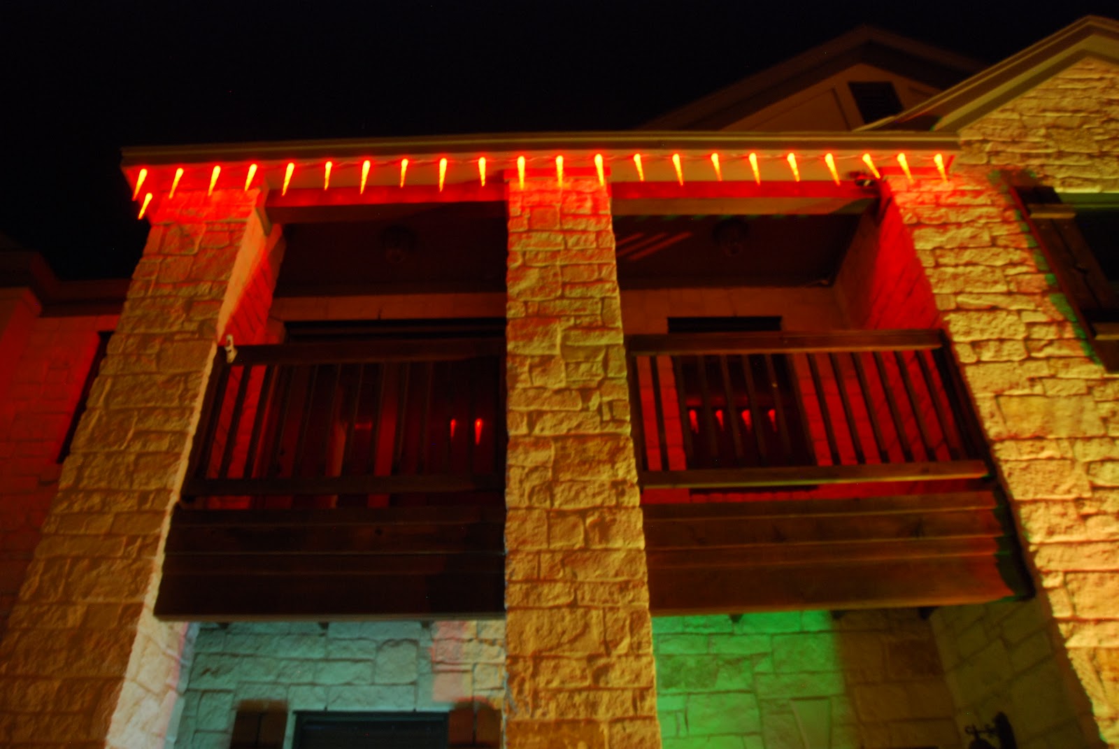
Whenever anyone tweeted @cheerlights or #cheerlights and a color, my house lights (just the deck icicles) changed to that color.
I was a bit of a rebel and decided to change to the tweeted color just for 1 minute instead of just leaving the lights constantly to the selected color. After 1 minute the stockplus program for GE G-35 Color Effects Lights written by sowbug (https://github.com/sowbug/G35Arduino) took over.
I couldn't resist not using the random mode: these lights are just amazing, and the effects are REALLY cool.
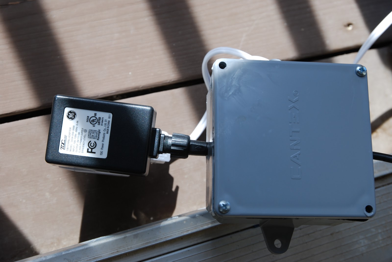
My setup was wireless. I used an ioBrigde module, xbee radios and an arduino to accomplish this.
The other cool part about this year's Christmas lights is that they were programmed to start/stop via a cronjob. I used the ioBridge x10 board and a bunch of x10 devices to accomplish this.
This year I joined a few other guys in the Cheerlights project.
CheerLights is an ioBridge Labsproject that allows people's lights all across the world to synchronize, stay linked based on social networking trends. It's a way to connect physical things with social networking experiences and spread cheer at the same time. We are all connected.
Whenever anyone tweeted @cheerlights or #cheerlights and a color, my house lights (just the deck icicles) changed to that color.
I was a bit of a rebel and decided to change to the tweeted color just for 1 minute instead of just leaving the lights constantly to the selected color. After 1 minute the stockplus program for GE G-35 Color Effects Lights written by sowbug (https://github.com/sowbug/G35Arduino) took over.
I couldn't resist not using the random mode: these lights are just amazing, and the effects are REALLY cool.
My setup was wireless. I used an ioBrigde module, xbee radios and an arduino to accomplish this.
The other cool part about this year's Christmas lights is that they were programmed to start/stop via a cronjob. I used the ioBridge x10 board and a bunch of x10 devices to accomplish this.
L’objectif de ce montage est de faire communiquer un PC avec une carte Arduino à l’aide du protocole ZigBee
Voici l’architecture de montage :
Cette article décrit la mise en place d’une topologie réseau simple, permettant de communiquer entre un PC et une carte Arduino à l’aide de modules XBee série 1 de chez Digi.
Les composants
Le montage nécessite les composants suivants :
un PC, fonctionnant sous Debian GNU/Linux pour ma part ;
une carte Arduino ou bien un adaptateur USB relié au PC ;
deux modules de communication XBee ;
une carte Arduino avec un adaptateur XBee.
A propos du protocole ZigBee
ZigBee est un protocole de haut niveau permettant la communication de petites radios, à consommation réduite, basée sur la norme IEEE 802.15.4 pour les réseaux à dimension personnelle (WPANs).
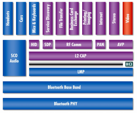
C’est vraiment un très bon protocole, qui est bien plus simple à mettre en œuvre que le protocole Bluetooth. Je ne sais pas si vous avez déjà vu la stack du protocole. Il y a de quoi avoir peur
xBee, ZigBee et beeee?
Si vous êtes perdus avec tous ces sigles, c’est normal. Moi aussi Voici ce que j’ai compris :
La connexion entre le module Xbee et un PC peut se faire de deux manières :
à l’aide d’un adaptateur USB ;
à l’aide d’une carte Arduino et d’un Shield XBee ;
L’objectif pour la partie PC du montage est de communiquer avec le module XBee, à fin de lui envoyer des commandes.
Cette communication se fait à l’aide d un convertisseur USB-Serial, ce rôle est joué par l’adaptateur USB ou bien par la carte Arduino + Shield.
Connexion à l’aide de l’adaptateur USB
L’adaptateur XBee se connect directement sur le port USB du PC :
Un fois branché, le module est visible à l’aide de la commande lsusb :
Bus 002 Device 013: ID 0403:6001 Future Technology Devices International, Ltd FT232 USB-Serial (UART) IC
Communication à l’aide d’une carte Arduino + XBee Shield
L’adaptateur XBee se connecte directement sur la carte Arduino :
Il est nécessaire de modifier la configuration par du shield pour mettre la carte en mode USB-Serial.
Pour cela, il faut mettre les deux jumper à droite (éloigner du port USB), comme sur cette photo : Configuration mode USB-serial
Vous pouvez ensuite brancher la carte Arduino et voir le module XBee à l’aide de la commande lsusb :
Bus 002 Device 013: ID 0403:6001 Future Technology Devices International, Ltd FT232 USB-Serial (UART) IC
Connexion à l’aide d’un gestionnaire de terminal
Une fois que le module XBee est connecté au PC, il doit être disponible sur /dev/ttyUSB0 :
[31016.280327] ftdi_sio 2-8.3:1.0: FTDI USB Serial Device converter detected

[31016.280354] /build/buildd/linux-2.6.24/drivers/usb/serial/ftdi_sio.c: Detected FT232RL

[31016.280449] usb 2-8.3: FTDI USB Serial Device converter now attached to ttyUSB0
Pour communiquer avec le module, il faut utiliser un programme de gestion de terminal ( gtkterm, minicom ou bien l’IDE de la carte Arduino).
Voici la configuration pour gtkterm :
Configuration du module XBee
Une fois que vous etes connecté au module XBee, vous pouvez lui envoyer des commandes à l’aide du gestionnaire de terminal.
Le module dispose de deux mode de fonctionnement : normal et configuration.
Pour passer en mode configuration, il faut saisir +++ (sans CR, retour à la ligne).
Si le module a compris la commande, alors il retourne OK.
Voici un exemple de session : .
Configuration d’un réseau bidirectionnelle simple
Voici les différentes instructions pour configurer un réseau simple, c’est à dire une communication bidirectionnelle entre deux cartes Arduino ou bien entre un PC et une carte Arduino
Configuration sur la carte reliée au PC
+++OK

ATMY1234

OK

ATDL5678

OK

ATDH0

OK

ATID1111

OK
Configuration du module Arduino
+++OK

ATMY5678

OK

ATDL1234

OK

ATDH0

OK

ATID1111

OK
Les commandes importantes sont :
ATMY : adresse source ;
ATDL : adresse de destination (bite de poids faible) ;
ATDH : adresse de destination (bite de poids fort) ;
ATID : identifiant du réseau ;
Utilisation au niveau de la carte Arduino
Il faut inscrire le programme suivant dans la mémoire de la carte :
void setup() {

  Serial.begin(9600);

  Serial.print("+++");

  Serial.print("ATDH0\r");

  Serial.print("ATDL1234\r");

  Serial.print("ATMY5678\r");

  Serial.print("ATID1111\r");

  Serial.print("ATCN\r");

}

void loop() {

   delay(1000);

   Serial.print("42\n");

}
La programmer et changer le sens des deux “jumper” pour faire communiquer le module avec la carte.
Planet Arduino is, or at the moment is wishing to become, an aggregation of public weblogs from around the world written by people who develop, play, think on Arduino platform and his son. The opinions expressed in those weblogs and hence this aggregation are those of the original authors. Entries on this page are owned by their authors. We do not edit, endorse or vouch for the contents of individual posts. For more information about Arduino please visit www.arduino.cc
You are currently browsing the archives for the xBee category.


