Posts | Comments

Planet Arduino

Archive for the ‘diy’ Category

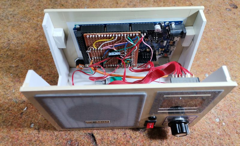
DIy Arduino FM radio enclosure with the lid off, showing the electronics inside

Older hackers will remember that a crystal set radio receiver was often one of the first projects attempted.  Times have changed, but there’s still something magical about gathering invisible signals from the air and listening to the radio on a homemade receiver. [mircemk] has brought the idea right up to date by building an FM radio with an OLED display, controlled with a rotary encoder.

The design is fairly straightforward, based as it is on another project that [mircemk] found on a Chinese site, but the build looks very slick and would take pride of place on any hacker’s workbench. An Arduino Due forms the heart of the project, controlling a TEA5767 module, an SH1106 128×64 pixel OLED display and a rotary encoder. The sound signal is passed through an LM4811 headphone amplifier for private listening, and a PAM8403 Class D audio amplifier for the built-in loudspeaker. The enclosure is made from PVC panels, and accented with colored adhesive tape for style.

It’s easier than ever before to quickly put together projects like this by connecting pre-built modules and downloading code from the Internet, but that doesn’t mean it’s not a worthwhile way to improve your skills and make some useful devices like this one. There are so many resources available to us these days and standing on the shoulders of giants has always been a great way to see farther.

We’ve shown some other radio projects using Arduinos and the TEA5767 IC in the past, such as this one on a tidy custom PCB, and this one built into an old radio case.

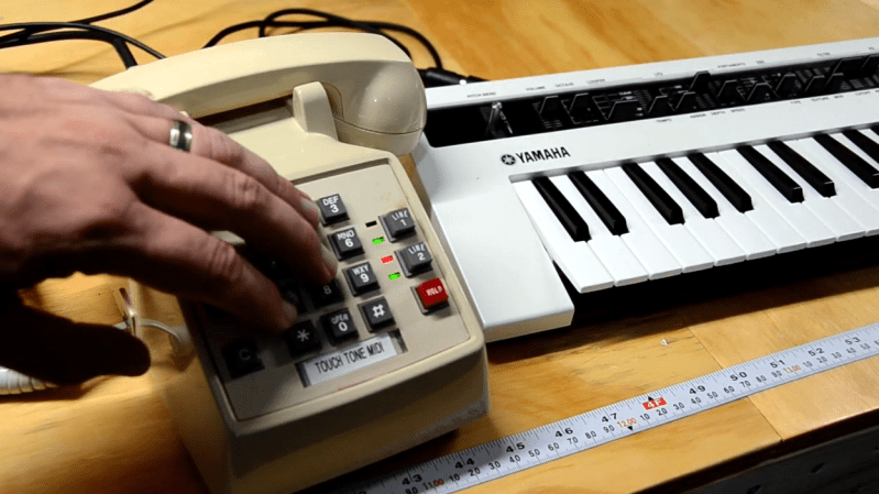
[poprhythm]’s Touch Tone MIDI Phone is a fantastic conversion of an old touch tone phone into a MIDI instrument complete with intact microphone, but this project isn’t just about showing off the result. [poprhythm] details everything about how he interfaced to the keypad, how he used that with an Arduino to create a working MIDI interface, and exactly how he decided — musically speaking — what each button should do. The LEDs on the phone are even repurposed to blink happily depending on what is going on, which is a nice touch.

Of course, it doesn’t end there. [poprhythm] also makes use of the microphone in the phone’s handset. Since the phone is now a MIDI instrument with both a microphone and note inputs, it’s possible to use them together as the inputs to vocoder software, which he demonstrates by covering Around the World by Daft Punk (video).

We love how [poprhythm] explains how he interfaced to everything because hardware work is all about such details, and finding the right resources. Here’s the GitHub repository for the Arduino code and a few links to other resources.

We have seen MIDI phone projects before, and each one is always unique in its own way: here’s a different approach to converting a keypad phone to MIDI, and this rotary pulse-dial phone went in a completely different direction with the phone itself completely unmodified, using only external interfacing.

You can admire [poprhythm]’s Touch Tone MIDI Phone in action in the short videos embedded below, with each one showing off a different aspect of the build. It’s great work!

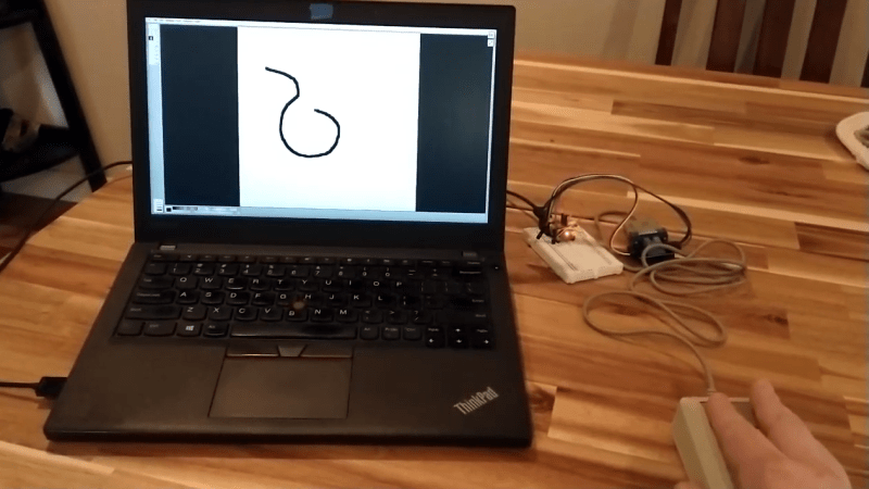
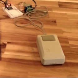
Need to hook a classic Mac mouse up to your modern machine with the help of a DIY USB adapter? [John Floren] has you covered. [John]’s solution uses a board with an ATmega32U4 microcontroller on it to connect to the Mac mouse on one end, and emulate a USB HID (Human Interface Device) on the other. A modern machine therefore recognizes it like it would any other USB input device.

Why is this necessary? The connector on the classic Mac mouse may look like a familiar DE-9 connector, but it is not an RS-232 device and wouldn’t work if it were plugged into a 9-pin serial port. The classic Mac mouse uses a different pinout, and doesn’t have much for brains on the inside. It relies on the host computer to read its encoders and button states directly.

This project is actually a bit of an update to a piece of earlier work [John] did in making a vintage Depraz mouse work with modern systems. He suspected that it wouldn’t take much to have it also work with a classic Mac mouse, and he was right — all it took was updating the pin connections and adding some pull-up resistors. The source code and design files are on GitHub.

Even if one does not particularly want to use a classic Mac mouse for daily work, there’s definitely value in this kind of thing for those who deal in vintage hardware: it allows one to function-check old peripherals without having to fire up a vintage machine.

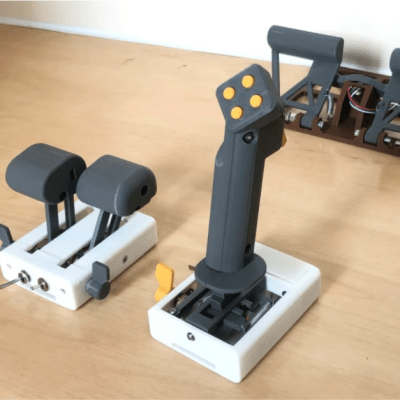
We have seen quite a few DIY joystick designs that use Hall effect sensors, but [Akaki]’s controller designs (YouTube video, embedded below) really make the most of 3D printing to avoid the need for any other type of fabrication. He’s been busy using them to enhance his Microsoft Flight Simulator 2020 experience, and shares not just his joystick design, but makes it a three-pack with designs for throttle and pedals as well.

Hall effect sensors output a voltage that varies in proportion to the presence of a magnetic field, which is typically provided by a nearby magnet. By mounting sensors and magnets in a way that varies the distance between them depending on how a control is moved, position can be sensed and communicated to a host computer. In [akaki]’s case, that communication is done with an Arduino Pro Micro (with ATmega32U4) whose built-in USB support allows it to be configured and recognized as a USB input device. The rest is just tweaking the physical layouts and getting spring or elastic tension right. You can see it all work in the video below.

Hall effect sensors have featured in DIY joystick builds, but for something as delightful as it is different, don’t miss this fantastic high-speed magnetic imager based on them.

If you’re one of the lucky ten thousand today who still haven’t tried programming electronics with the Arduino platform, this detailed guide by [Dafna Mordechai] should hopefully give you enough incentive to pick it up now and make a simple bit of Christmas-themed decoration with it.

The guide isn’t exactly aimed at complete ground-up beginners but it does give some pointers on where to look up whatever information you don’t have in order to follow along. Other than that, it’s very simple and has well-detailed steps, showing you how to turn a breadboard into a simple animated arrangement of LEDs in the shape of a Christmas tree, along with a piezo buzzer playing “Jingle Bells”. If you’ve never done this sort of stuff before, [Dafna] explains in pretty good detail which part of the code does what, making it pretty simple if you want to play around with it and customize it to your taste.

Once you’ve gotten the hang of the basics of Arduino, why not try a project that’s a little more elaborate? Without having to stray too far from your comfort zone, you can easily build a kid’s toy full of switches and lights or even a very extra clock that has no shortage of lights and dials.

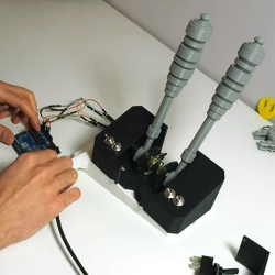
One of the more interesting ideas being experimented with in VR is 1:1 mapping of virtual and real-world objects, so that virtual representations can have physically interaction in a normal way. Tinker Pilot is a VR spaceship simulator project by [LLUÍS and JAVI] that takes this idea and runs with it, aiming for the ability to map a cockpit’s joysticks, switches, and other hardware to real-world representations. What does that mean? It means a virtual cockpit with flight sticks, levers, and switches that have working physical versions that actually exist exactly where they appear to be.

A few things about the project design caught our eye. One is the serial communications protocol intended to interface easily with microcontrollers, allowing for feedback between the program and any custom peripherals. (By the way, this is the same approach Kerbal Space Program took with KSPSerialIO, which enables custom mission control hardware at whatever level of complexity a user may wish to implement.)

The possibilities are demonstrated starting around 1:09 in the teaser trailer (embedded below) in which a custom controller is drawn up in CAD, then 3D-printed and attached to an Arduino, and finally the 3D model is imported into the cockpit as a 1:1 representation of the actual working unit, with visual positional feedback.

Unlike this chair experiment we saw which attached a Vive Tracker to a chair, there is no indication of needing positional trackers on individual controls in Tinker Pilot. In a cockpit layout, controls can be reasonably expected to remain in fixed positions relative to the cockpit, meaning that they can be set up as 1:1 representations of a physical layout and otherwise left alone. The kind of experimentation that is available today even to individual developers or small teams is remarkable, and it’s fascinating to see the ideas being given some experimentation.

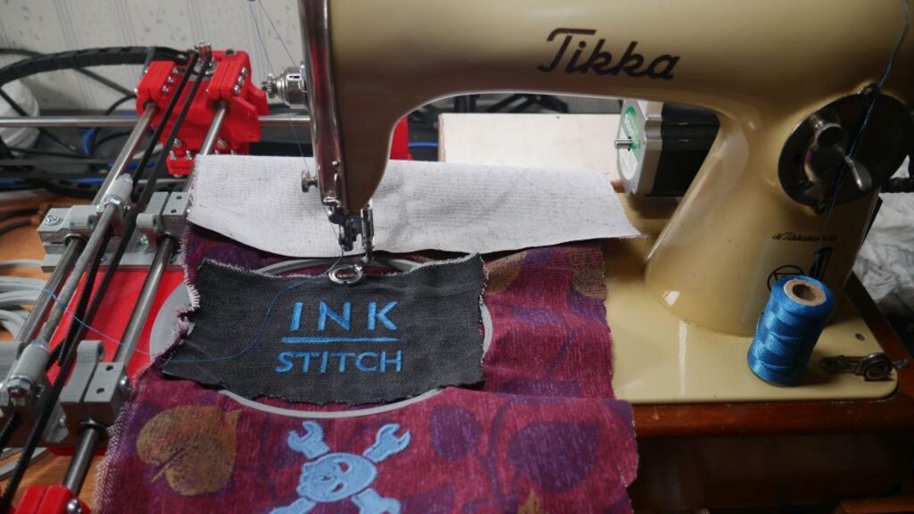
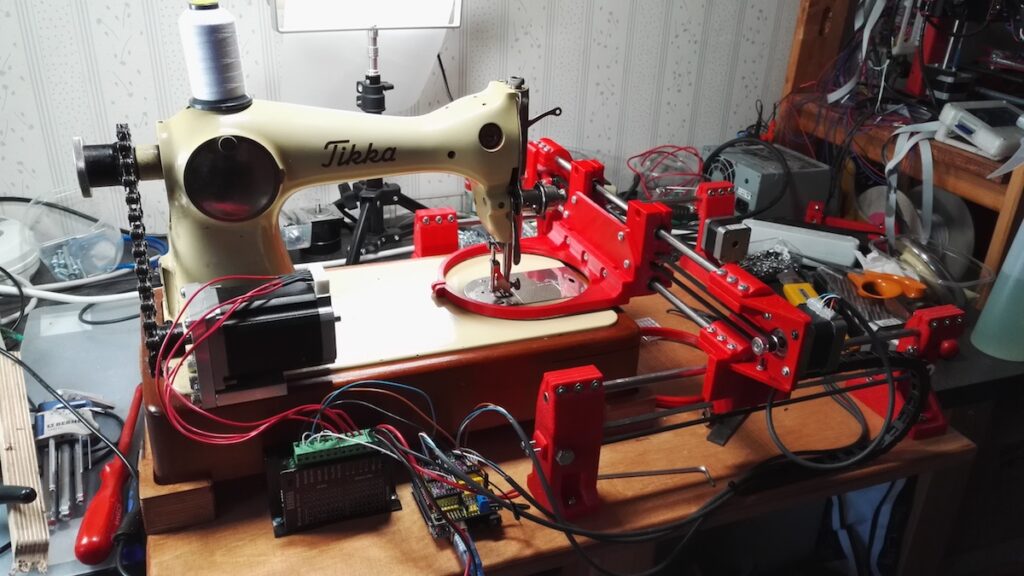
A needle and thread is extremely useful if you need to fasten a few pieces of fabric or sew on a button, and a sewing machine takes things up several notches in speed an accuracy. This venerable machine, however, can now be enhanced with a trio of stepper motors under Arduino Uno GRBL control to take things to an entirely new level.

The “Self-Made Embroidery Machine” employs a setup very similar to a 3D printer or CNC router. Two steppers move the fabric around, while a third actuates the needle. This allows the user to program in decorative shapes and patterns as shown in the video below, and the build process is well documented if you’d like to create your own!

Sewing machine part is any old or new sewing machine. Only change for original is stepper motor with synchronised pulley system (chain/belt drive) and more embroidery friendly presser foot. It is recommended to use older sewing machine, way more convenient to mount stepper motor to cast iron and prices are relatively cheap.

XY movement consists mainly 3D printed parts, 12 pcs and similar parts known from self build 3D printers. Both axes use GT2 belts, NEMA 17 steppers and both directions are fully scalable.

Synchronous movement comes from Arduino powered GRBL G-code interpreter, it is mouthful, but basically machine moves using G-code send to Arduino. It is not that complicated and it is only carrier like any other one when going from system to another one.

Now we have movement and code, but how to make nice shapes and export to G-code. It is nothing to do with medieval sorcery, it is a matter of downloading Inkscape and extension called Inkstitch.

Help and examples how to use Inkstitch extension can be found address above. End result should be really close to hobby level embroidery machines, just slower speed. After all, embroidery machine is nothing more than overgrown sewing machine.

Puff and Suck (or Sip and Puff) systems allow people with little to no arm mobility to more easily interact with computers by using a straw-like unit as an input device. [Ana] tells us that the usual way these devices are used to input text involves a screen-based keyboard; a cursor is moved to a letter using some method (joystick, mouse emulator, buttons, or eye tracking) and that letter is selected with a sip or puff into a tube.

[Ana] saw such systems as effective and intuitive to use, but also limited in speed because there’s only so fast that one can select letters one at a time. That led to trying a new method; one that requires a bit more work on the user’s part, but the reward is faster text entry. The Puff-Suck Interface for Fast Text Input turns a hollow plastic disk and a rubber diaphragm into bipolar pressure switch, able to detect three states: suck, puff, and idle. The unit works by having an IR emitter and receiver pair on each side of a diaphragm (one half of which is shown in the image above). When air is blown into or sucked out of the unit, the diaphragm moves and physically blocks one or the other emitter-receiver pair. The resulting signals are interpreted by an attached Arduino.

How does this enable faster text input? By throwing out the usual “screen keyboard” interface and using Morse code, with puffs as dots and sucks as dashes. The project then acts as a kind of Morse code keyboard. It does require skill on the user’s part, but the reward is much faster text entry. The idea got selected as a finalist in the Human-Computer Interface Challenge portion of the 2018 Hackaday Prize!

Morse code may seem like a strange throwback to some, but not only does the bipolar nature of [Ana]’s puff-suck switch closely resemble that of Morse code input paddles, it’s also easy to learn. Morse code is far from dead; we have pages of projects and news showing its involvement in everything from whimsical projects to solving serious communication needs.

Lab equipment is often expensive, but budgets can be tight and not always up to getting small labs or researchers what they need. That’s why [akshay_d21] designed an Open Source Lab Rocker with a modular tray that uses commonly available hardware and 3D printed parts. The device generates precisely controlled, smooth motion to perform automated mild to moderately aggressive mixing of samples by tilting the attached tray in a see-saw motion. It can accommodate either a beaker or test tubes, but since the tray is modular, different trays can be designed to fit specific needs.

Source code and schematics are available from [akshay_d21]’s Google Drive and the 3D models are also available from the National Institute of Health’s 3D Print Exchange. A demonstration video is embedded below, in which you can see how smooth and controlled the motions are.

DIY lab equipment really benefits from the recent growth in desktop manufacturing and part availability; this one is in good company along with the DIY Laboratory Dry Bath and this DIY Syringe Pump.

In a project, repetitive tasks that break the flow of development work are incredibly tiresome and even simple automation can make a world of difference. [Simon Merrett] ran into exactly this while testing different stepper motors in a strain-wave gear project. The system that drives the motor accepts G-Code, but he got fed up with the overhead needed just to make a stepper rotate for a bit on demand. His solution? A grbl man-in-the-middle jog pendant that consists of not much more than a rotary encoder and an Arduino Nano. The unit dutifully passes through any commands received from a host controller, but if the encoder knob is turned it sends custom G-Code allowing [Simon] to dial in a bit acceleration-controlled motor rotation on demand. A brief demo video is below, which gives an idea of how much easier it is to focus on the nuts-and-bolts end of hardware when some simple motor movement is just a knob twist away.

[Simon]’s jog pendant moves a single motor which is exactly what he needs to ease development of his 3D printed strain-wave gear using a timing belt, but it could be programmed with any G-Code at all. Speaking of DIY jog pendants for CNC machines, don’t forget this wireless one made from an Atari 2600 joystick that jogs a plasma cutter in X and Y, and zeroes it with a push of the button.


Filed under: Arduino Hacks, cnc hacks


  • Newsletter

    Sign up for the PlanetArduino Newsletter, which delivers the most popular articles via e-mail to your inbox every week. Just fill in the information below and submit.

  • Like Us on Facebook