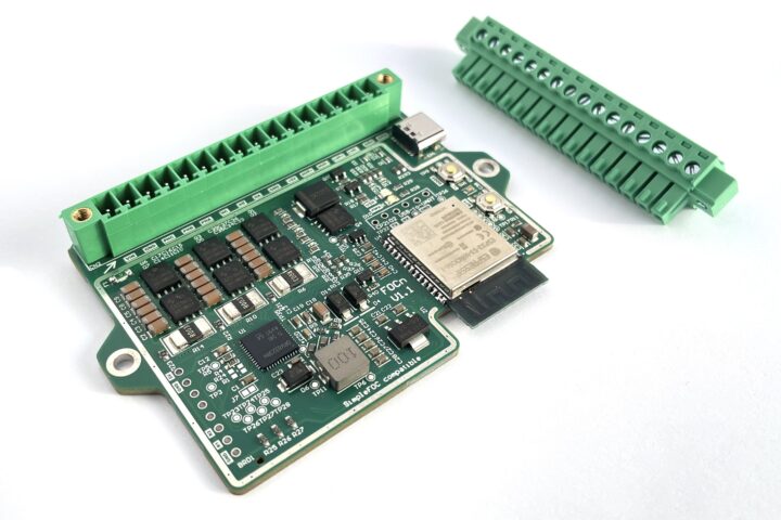
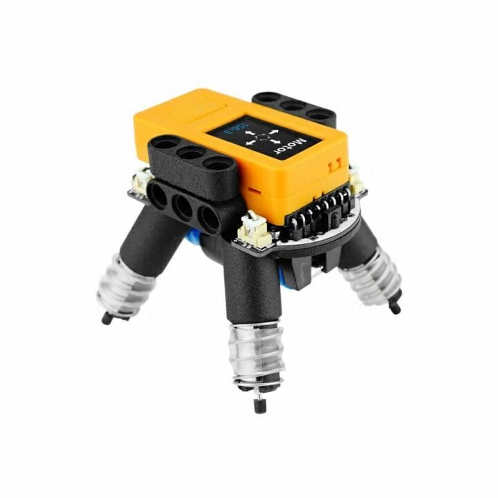
Posts | Comments

Planet Arduino

Archive for the ‘Hardware’ Category

"The Great Resistor" color code illumination project

With surface-mount components quickly becoming the norm, even for homebrew hardware, the resistor color-code can sometimes feel a bit old-hat. However, anybody who has ever tried to identify a random through-hole resistor from a pile of assorted values will know that it’s still a handy skill to have up your sleeve. With this in mind, [j] decided to super-size the color-code with “The Great Resistor”.

Resistor color code from Wikipedia with white background
How the resistor color-code bands work

At the heart of the project is an Arduino Nano clone and a potential divider that measures the resistance of the test resistor against a known fixed value. Using the 16-bit ADC, the range of measurable values is theoretically 0 Ω to 15 MΩ, but there are some remaining issues with electrical noise that currently limit the practical range to between 100 Ω and 2 MΩ.

[j] is measuring the supply voltage to help counteract the noise, but intends to move to an oversampling/averaging method to improve the results in the next iteration.

The measured value is shown on the OLED display at the front, and in resistor color-code on an enormous symbolic resistor lit by WS2812 RGB LEDs behind.

Inside view of the great resistor showing WS2812 LEDs and baffle plates
Inside The Great Resistor, the LEDs and baffle plates make the magic work

Precision aside, the project looks very impressive and we like the way the giant resistor has been constructed. It would look great at a science show or a demonstration. We’re sure that the noise issues can be ironed out, and we’d encourage any readers with experience in this area to offer [j] some tips in the comments below. There’s a video after the break of The Great Resistor being put through its paces!

If you want to know more about the history of the resistor color code bands, then we have you covered.  Alternatively, how about reading the color code directly with computer vision?

A diagram showing an LED on the left, a lever-style plumbing valve in the center, and an Arduino Uno on the right.

Input devices that can handle rough and tumble environments aren’t nearly as varied as their more fragile siblings. [Alastair Aitchison] has devised a brilliant way of detecting inputs from plumbing valves that opens up another option. (YouTube) [via Arduino Blog]

While [Aitchison] could’ve run the plumbing valves with water inside and detected flow, he decided the more elegant solution would be to use photosensors and an LED to simplify the system. This avoids the added cost of a pump and flow sensors as well as the questionable proposition of mixing electronics and water. By analyzing the change in light intensity as the valve closes or opens, you can take input for a range of values or set a threshold for an on/off condition.

[Aitchison] designed these for an escape room, but we can see them being great for museums, amusement parks, or even for (train) simulators. He says one of the main reasons he picked plumbing valves was for their aesthetics. Industrial switches and arcade buttons have their place, but certainly aren’t the best fit in some situations, especially if you’re going for a period feel. Plus, since the sensor itself doesn’t have any moving parts, these analog inputs will be easy to repair should anything happen to the valve itself.

If you’re looking for more unusual inputs, check out the winners of our Odd Inputs and Peculiar Peripherals contest or this typewriter that runs Linux.

The story of how [Tony]’s three-wheeled electric scooter came to be has a beginning that may sound familiar. One day, he was browsing overseas resellers and came across a new part, followed immediately by a visit from the Good Ideas Fairy. That’s what led him to upgrade his DIY electric scooter to three wheels last year, giving it a nice speed boost in the process!

The part [Tony] ran across was a dual brushless drive unit for motorizing a mountain board. Mountain boards are a type of off-road skateboard, and this unit provided two powered wheels in a single handy package. [Tony] ended up removing the rear wheel from his electric scooter and replacing it with the powered mountain board assembly.

He also made his own Arduino-based interface to the controller that provides separate throttle and braking inputs, because the traditional twist-throttle of a scooter wasn’t really keeping up with what the new (and more powerful) scooter could do. After wiring everything up with a battery, the three-wheeled electric scooter was born. It’s even got headlights!

[Tony]’s no stranger to making his own electric scooters, and the fact that parts are easily available puts this kind of vehicular experimentation into nearly anybody’s hands. So if you’re finding yourself inspired, why not order some stuff, bolt that stuff together, and go for a ride where the only limitation is personal courage?

The PCB business card has long been a way for the aspiring electronics engineer to set themself apart from their peers. Handing out a card that is also a two player game is a great way to secure a couple minutes of a recruiter’s time, so [Ryan Chan] designed a business card that, in addition to his contact information, also has a complete Tic-Tac-Toe game built in.

[Ryan] decided that an OLED display was too expensive for something to hand out and an LED matrix too thick, so he decided to keep it simple and use an array of 18 LEDs—9 in each of two colors laid out in a familiar 3×3 grid. An ATmega328p running the Arduino bootloader serves as the brains of the operation. To achieve a truly minimal design [Ryan] uses a single SMD pushbutton for control: a short press moves your selection, a longer press finalizes your move, and a several-second press switches the game to a single-player mode, complete with AI.

If you’d like to design a Tic-Tac-Toe business card for yourself, [Ryan] was kind enough to upload the schematics and code for his card. If you’re still pondering what kind of PCB business card best represents you, it’s worth checking out cards with an updatable ePaper display or a tiny Tetris game.

Thanks to [Abe] for the tip!

Drums are an exciting instrument to learn to play, but often prohibitive if there are housemates or close neighbors involved. For that problem there are still electronic drums which can be played much more quietly, but then the problem becomes one of price. To solve at least part of that one, [Jeremy] turned to using an Arduino to build a drum module on his own, but he still had to solve yet a third problem: how to make the Arduino fast enough for the drums to sound natural.

Playing music in real life requires precise timing, so the choice of C++ as a language poses some problems as it’s not typically as fast as lower-level languages. It is much easier to work with though, and [Jeremy] explains this in great detail over a series of blog posts detailing his drum kit’s design. Some of the solutions to the software timing are made up for with the hardware on the specific Arduino he chose to use, including an even system, a speedy EEPROM, hardware timers, and an ADC that can sample at 150k samples per second.

With that being said, the hardware isn’t the only thing standing out on this build. [Jeremy] has released the source code on his GitHub page for those curious about the build, and is planning on releasing several more blog posts about the drum kit build in the near future as well. This isn’t the only path to electronic drums, though, as we’ve seen with this build which converts an analog drumset into a digital one.

Step sequencers are fantastic instruments, but they can be a little, well, repetitive. At it’s core, the step sequencer is a pretty simple device: it loops through a series of notes or phrases that are, well, sequentially ordered into steps. The operator can change the steps while the sequencer is looping, but it generally has a repetitive feel, as the musician isn’t likely to erase all of the steps and enter in an entirely new set between phrases.

Enter our old friend machine learning. If we introduce a certain variability on each step of the loop, the instrument can help the musician out a bit here, making the final product a bit more interesting. Such an instrument is exactly what [Charis Cat] set out to make when she created the After Eight Step Sequencer.

The After Eight is an eight-step sequencer that allows the artist to set each note with a series of potentiometers (which are, of course, housed in an After Eight mint tin). The potentiometers are read by an Arduino, which passes MIDI information to a computer running the popular music-oriented visual programming language Max MSP. The software uses a series of Markov Chains to augment the musician’s inputted series of notes, effectively working with the artist to create music. The result is a fantastic piece of music that’s different every time it’s performed. Make sure to check out the video at the end for a fantastic overview of the project (and to hear the After Eight in action, of course)!

[Charis Cat]’s wonderful creation reminds us of some the work [Sara Adkins] has done, blending human performance with complex algorithms. It’s exactly the kind of thing we love to see at Hackaday- the fusion of a musician’s artistic intent with the stochastic unpredictability of a machine learning system to produce something unique.

Thanks to [Chris] for the tip!

There’s a brand new device-to-device communication feature available now in the Arduino IoT Cloud. It’s something we’ve been working on for a long time. So we’re excited to see how it’ll add a whole new connected dimension to your Arduino projects.

Arduino IoT Cloud thing to thing communication

What is “Device-to-Device”? Communication?

Internally we’ve been looking at this feature as “device-to-device” communication. It will allow your Arduino devices to send wireless messages to each other, without writing a single line of code or spending time with radio modules and network protocols.

Using this feature you can link variables of the same data type between two or more cloud-enabled devices. For example, one button could set three smart bulbs to the same color. Or you could turn on a heater when temperature sensors in your room or outside in your weather station drop below a certain level. Being able to sync variables gives you an intelligent way to control multiple devices very easily.

Whether you use an Oplà IoT Kit, a MKR WiFi 1010, a Nano 33 IoT or an (upcoming!) Nano RP2040 Connect, you can configure everything from the web interface. After configuration, any changes you make to variables on one device will be reflected promptly on the other(s). This creates a seamless, powerful and secure two-way communication with almost no effort on your part, and no code required. The Arduino IoT Cloud handles authentication, security, network disruptions and any other tricky parts. 

What Does This Mean For Your Projects and Devices?

It means there are lots of options with thing-to-thing communication (also known as variable synchronization):

  • Collect sensor readings from remote devices.
  • Actuate devices remotely. For instance, pressing a button on one Arduino turns on an LED or motor on another.
  • Create a distributed algorithm where multiple devices collaborate with each other.

Are you thinking about home automation? Interactive installations? Monitoring and controlling machines from a wireless panel? This powerful new feature makes all those things easy to achieve for makers of all abilities.

Arduino Cloud thing to thing dashboard.

Combined with IoT Cloud’s dashboards this delivers a powerful new way to build incredible automations with minimal (if any) changes. Furthermore, it gives you smartphone control of your connected boards via the existing Arduino IoT Remote iOS and Android apps.

If you want to be one of the first to try it out, grab an Arduino IoT Cloud subscription. After that, just make sure you’re signed up to the Arduino newsletter to hear about other new features.

The post It’s easier than ever to add two-way communication to Arduino devices appeared first on Arduino Blog.

By popular demand, we are pleased to announce that it’s now possible to buy the Arduino MKR IoT Carrier. Originally forming a key part of the Arduino Oplá IoT Kit, we’ve responded to our community to make the carrier available on it’s own, thus enabling you to benefit from having a bunch of sensors, actuators and a display all featured on the one board — making it quicker and easier to take your IoT projects to the next level.

Featuring a large set of built-in sensors and actuators as well as a useful color display, the carrier lets you focus on prototyping your IoT ideas right away by saving on the hassle of wiring and soldering these components.  

The carrier can become a WiFi, LoRa, NB-IoT or GSM-compatible device by seamlessly connecting to any MKR family board. Building a user interface for these boards is easy with the embedded color OLED screen, five capacitive touch buttons, and the five RGB LEDs. The integrated sensors (temperature, humidity, pressure, RGBC light, gesture and proximity) allow you to map the environment around the carrier, and should you need to capture any other data there are over 100 additional Grove sensors that can easily be connected directly to the carrier.

Here’s are quick demo of the carrier’s capabilities! (Special shout out to Mirko Pacioni and Fill Connesso for creating this demo.)

Capture and store all the data locally on an SD card, or connect your MKR family board to the IoT Cloud for real-time data captured, storage, and visualization.

The MKR IoT Carrier features:

  • Round OLED display
  • Five RGB LEDs
  • Five capacitive touch buttons
  • On-board sensors (temperature, humidity, pressure, RGBC light, gesture and proximity)
  • Buzzer
  • IMU (Three-axis accelerometer sensor and three-axis gyroscope sensor)
  • Two 24V relays
  • MicroSD card holder (SD card not included)
  • Plug-and-play Grove connectors for external sensors — two analog and one digital (I2C)
  • 18650 Li-ion rechargeable battery holder (battery not included)

The MKR IoT Carrier is now available to purchase from the Arduino online store for €48 / $57.60 — find infinite possibilities for all your IoT projects

Interested in learning how to build IoT projects, then we have the perfect choice of kits for you, both featuring the MKR IoT Carrier. The Arduino Explore IoT Kit is the ideal kit to learn about the Internet of Things and what you can do with it, while the Arduino Oplá IoT Kit is great for experiencing the benefits of IoT at home or in the office with eight out-of-the-box IoT projects controlled on the Arduino IoT Cloud


  • Newsletter

    Sign up for the PlanetArduino Newsletter, which delivers the most popular articles via e-mail to your inbox every week. Just fill in the information below and submit.

  • Like Us on Facebook